This paper is a continuation of Dana Riddle’s first article: Light Data from a Hawaiian Tidepool
There are many variables to consider when deciding which lighting system to purchase or how to utilize that light. While light intensity can be estimated visually (with experience) or, much better, quantified with a PAR meter, accurately gauging spectral qualities requires specialized equipment. Fortunately, my small laboratory has the devices available to analyze both light intensity and spectral quality. If we coordinate collection of the two, we can perform many calculations, with the results being of interest to dedicated hobbyists. Specifically, we can examine the dose of various bandwidths (e.g., blue, green, red light) falling upon corals in a shallow Hawaiian tide pool and compare these to light received by corals in captivity.
I had pondered for some time the logistics of combining these data, and the invitation to present at the 2013 Marine Aquarium Conference of North America (MACNA) in Fort Lauderdale was the impetus for finally launching the projects and collecting necessary information. I had accepted the invitation to speak in Florida, and the race was on. Just a few months remained before conference and I realized all my ‘spare’ time would have to be devoted to these projects.
In an article published (www.advancedaquarist.com/2013/9/aafeature) we established that it is possible to match the amount of natural light within an aquarium. But what of spectral qualities? This article will detail the procedures and results.
Protocol
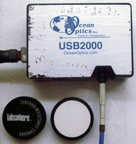
Figure 1. The Ocean Optics USB2000 spectrometer used in these experiments and reflectance standard. The spectrometer is a sturdy instrument and has given over a decade of reliable service.
Spectral data were collected with an Ocean Optics USB2000 spectrometer and SpectraSuite™ software (Ocean Optics, Dunedin, Florida, USA). This device consists of a diffraction grating and Sony IXL511 linear silicon CCD array with 2,048 pixels, all within a housing about the size of a deck of playing cards. It is attached to, and draws its power from, a computer via a USB cable. This makes it highly portable and suitable for fieldwork. Small fiber optic cables can be attached which allow spectral data to be collected in shallow water. See Figure 1. The fiber optic cable was positioned at a 45 angle to a 99% diffuse reflectance standard (Spectralon; Labsphere, North Sutton, New Hampshire, USA).
Thousands of data points were collected. See Figure 2 shows one spectral quality snapshot of an underwater light field (2″ depth) in February 2013.
The information in Figure 2 is pretty but doesn’t tell us much; hence it was exported to another Excel program for further analyses. Easier said than done. The Ocean Optics spectrometer ‘sees’ light at 3 or 4 points per nanometer, and this information must be interpolated to 1 nanometer increments. This involved writing a ‘sum and average’ program for random groups of 3 or 4 data points (and the spectrometer reports approximately 2,000). See Figure 3.
This program then divided collected data into the following bandwidths:
- Violet: 400 – 430 nm
- Blue: 431 – 480 nm
- Green-Blue: 481 – 490 nm
- Blue-Green: 491 – 510 nm
- Green: 511 – 530 nm
- Yellow-Green: 531 – 570 nm
- Yellow: 571 – 580 nm
- Orange: 581 – 600 nm
- Red: 601 – 700 nm
The program then calculated the percentage of light in each bandwidth. See Figure 4 for graphical data.
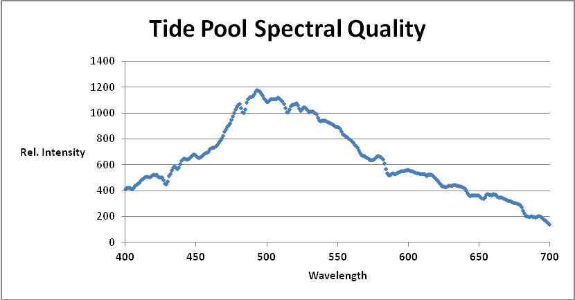
Figure 3. Numerical data from SpectraSuite™ is interpolated to 1 nanometer increments by a specially written Excel program. This is a snapshot of underwater spectral data at 7:30 am. Almost 50 of these data sets were combined in order to visualize time-course spectral qualities in a Hawaiian tide pool.
| Color | Percentage |
|---|---|
| Violet | 7.5655% |
| Blue | 18.818% |
| Green-Blue | 5.519% |
| Blue-Green | 11.585% |
| Green | 10.756% |
| Yellow-Green | 17.671% |
| Yellow | 3.351% |
| Orange | 5.728% |
| Red | 19.008% |
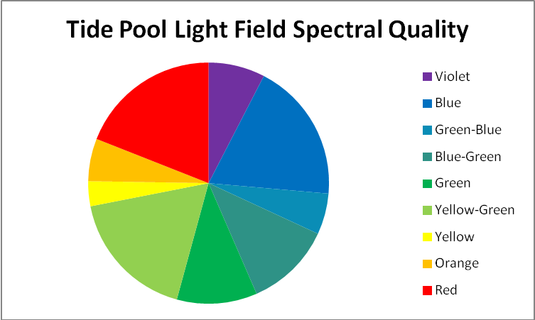
Figure 4. Spectral quality of light at 7:30am at a depth of 2 inches (5 cm) in the tide pool. The percentages are also shown in a table. See Table 1.
Once percentages were determined, they would be used to determine Spectral Daily Light Integral (DLI) by multiplying the amount of Photosynthetic Photon Flux Density (PPFD) by percentage per bandwidth. This requires knowing the PAR values. A WatchDog data logger and PAR sensors (Aurora, Illinois, USA) were deployed and collected PPFD data above the water line and at a depth of 2 inches. Wind and wave action created ‘glitter lines’ and made the light field irregular starting mid-morning and ending late afternoon. A polynomial trend line was added to estimate underwater light intensity. See Figure 5.
Since thousands of data points were collected, I decided to use information collected at the moment of sunrise and every 15 minutes thereafter until sunset.
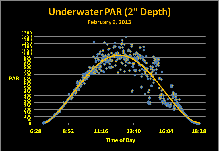
Figure 5. Light intensity data from the shallow tide pool.
If we multiply the PAR values by the percentage of light per bandwidth (taken at 15 minute increments), we are able to estimate the amount of light per color over the course of a day. See Figure 6.
We are not done quite yet. The data shown in Figure 6 can be further refined by calculating the:
Daily Light Integral: The Daily Light Integral is the total amount of light (or Photosynthetic Photon Flux Density, or PPFD) falling on a given area during the entire photoperiod. The best comparison is to compare PPFD to rainfall. An instantaneous PPFD value (the number of photons falling on a given surface area in a given amount of time) is equivalent to the number of raindrops falling on an equal area and time. We would find a weather report presenting rainfall as number of raindrops falling on a square meter per second to be practically useless. We are more interested in the total amount of rainfall reported in inches or centimeters. The same is true for light – we should be interested in the total number of photons in a given photoperiod.
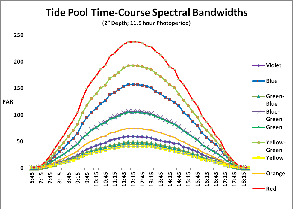
Figure 6. We can easily see the amount of PAR in each color of the visible spectrum. For instance, red light bandwidth peaks at a PAR value of about 235 µmol·m²·second, while blue peaks at around 160 µmol·m²·second.
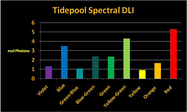
This article will carry DLI a step further – they will be calculated for spectral bandwidths (e.g., blue, green, red, etc.) as described in the ‘Protocol’ section (above). We simply sum the number of photons per bandwidth. The results are shown in Figure 7.
Now that we know the amount of light per color, we can compare them to that light produced by an artificial lamp). The procedure outlined above was repeated for a LED fixture from Build My LED. See Figures 8 and 9.
Discussion
Under the conditions of these experiments, it is obvious that corals within an aquarium can receive more blue light than in nature while being deficient in other colors. In this case, the corals received about 65% more blue light than in the shallow tidepool (this is based on the following data from the aquarium: 12-hour photoperiod at an intensity of ~250 µmol·m²·sec.)
In another experiment (www.advancedaquarist.com/2013/9/aafeature) we found that it is possible in a well-lighted aquarium to achieve, and even exceed, the amount of light naturally received by a shallow-water Hawaiian coral in the winter. Light intensity varies with the season, and summer DLI values in the tidepool are likely about double those seen in the winter (something on the order of ~22 winter DLI and ~45 summer DLI; see Hill et al., 2012 for further details).
Now that we have established light intensity and its spectral components, we can look at how this light affects corals in captivity.

Figure 8. Spectral signature of a custom-built LED fixture containing those generating light at a maximum of mostly blue light at 450nm and 470nm, with 4,500K ‘neutral whites’.
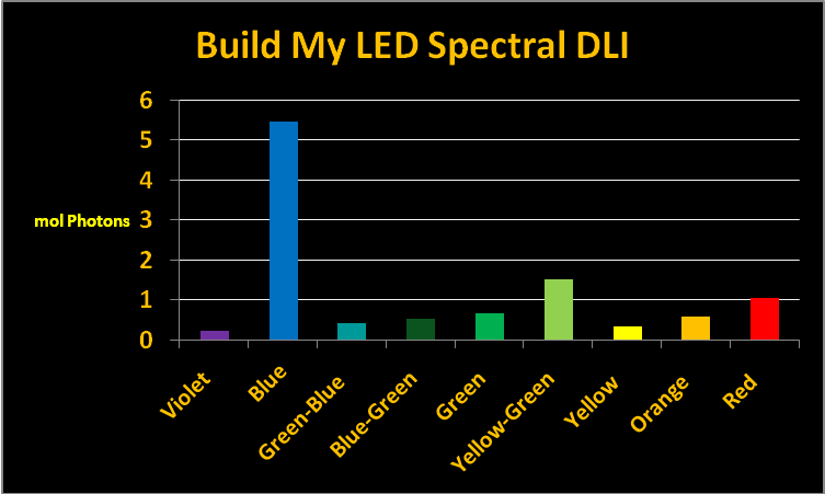
Figure 9. The amount of light, divided into “color bandwidths” to which the corals in the testing were exposed.
Reference
- Hill, R., A. Larkum, O. Prášil, D. Kramer, M. Szabó, V. Kumar, and P. Ralph, 2012. Light-induced dissociation of antenna complexes in the symbionts of scleractinian corals correlates with sensitivity to coral bleaching. Coral Reefs, 31: 963-975.
Acknowledgements
Many thanks to Build My LED for donating LED fixtures used in these experiments. See: www.buildmyLED.com
Kudos to Charlie Mazel for versing me on use of the spectrometer. See his site at www.nightsea.com



0 Comments