Light plays a vital role in the success of keeping corals in an aquarium. Light drives photosynthesis and plays an important role in the overall health of corals. The lighting system of a reef aquarium is one of the most argued about and one of the most expensive components. In addition to initial cost, light systems are the largest contributor to running costs of aquariums and a large source of unwanted heat. Clearly from the hobbyist’s perspective finding the most cost effective way to light the tank is often an important concern. Balancing the needs of corals, costs and aesthetics all come into play when deciding on a lighting system.
The physical aspects of light that are of interest to us are 1) Spectral Quality and 2) Intensity. Some earlier work has focused on determining the spectral characteristics of the various metal halide lamps, in an effort to provide data that could be useful to match the needs of the corals to the spectral output of the lamps, as well as the aesthetics of the aquarium (References 1-7). In addition to spectral quality, the intensity of light is also important. Light intensity for our purpose is the intensity of light available for photosynthesis (in the 400-700 nm wavelengths). For a detailed overview of light measurements see (References 1-7). Intensity of light is measured as Photosynthetic Photon Flux Density (PPFD) or Photosynthetically Available Radiation (PAR), and units used are μmol/sec/m2. For our purpose here, all references to light intensity refer to PPFD.
One obvious way to increase the optical output of the light source is to use a bigger lamp. However, using a higher output light source will not always result in higher optical output on the area of concern (in our case the surface of the water in the aquarium). Since light is emitted in all directions (although not equally in all directions for a Metal Halide lamp), what is important is not what is emitted but what is collected and re-directed to the surface of interest. Reflectors are used to collect and re-direct light.
Reflectors should be an integral part of any lighting system considered by the aquarist, since they play a vital role in establishing the intensity and light distribution over the aquarium. Half the light emanating from a lamp (in horizontal orientation) is in the upward direction, and a reflector helps direct this light downwards to the area where it is needed. The ideal scenario is all light emitted by the source is re-directed by the reflector profile. Light then exits in a well defined cone.
Reflectors available in the hobby fall into two distinct categories:
- DIY or stand alone type – designed for assembly into an existing aquarium hood.
- Luminaries – completely assembled lighting fixtures with integrated reflectors (and other accessories, e.g. UV protective glass, lenses, housing etc.).
In this article we report on the analysis of several commercial reflectors designed for mogul lamps and for use in a canopy.
The objective here is to understand light distribution and intensity, as a function of the different reflectors, on the surface of the tank. Although it would be considerably more useful to know the light intensity under water, it is a lot more difficult and complicated as a measurement task. As a first step, let us get a better understanding of the light field on the surface of the aquarium.
Basic Laws of Reflection
All reflection principles follow Snell’s Law:
- The angle of incidence is equal to the angle of reflection. (figure 1)
- The incident ray, the normal, and the reflected ray are coplanar.
Characteristics distinguishing reflectors:
- Type of reflection – Specular/Diffuse
- Reflector geometry/shape
- Positioning of the lamp
Type of Reflection
- Specular Reflection
- Refers to reflection where parallel incident rays of light on a surface are reflected parallel, and any material that reflects light in this manner is called a specular reflector. Examples of specular reflective material are mirrors and polished aluminum. These materials all posses what we would typically consider smooth and shiny surfaces.
- Diffuse Reflection
- Occurs when the reflective surface is rough (on a microscopic level) and parallel incident rays on such a surface are no longer parallel when reflected. Surfaces that cause diffuse reflection also obey the laws of reflection.
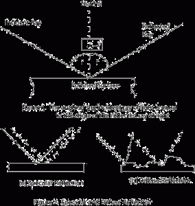
In the real world there is no such thing as a surface that will yield a perfect specular reflection since it is impossible to polish a surface to a level where there are no facets (a small planar surface) at an atomic level. Various materials used as reflector have different amounts of specular and diffuse reflection. It is not the intent of this article to analyze different materials, but rather to look at the resulting effect of reflector material choice and design on light distribution. For a further discussion on this see [8].
Reflector Geometry and Shape
The geometry and shape of the reflector plays an important role in both light intensity and light distribution. It determines how the focus of a shape is created with regard to the rays of light bouncing off the surface. Some commonly used shapes are parabolic, elliptical, spherical, etc.
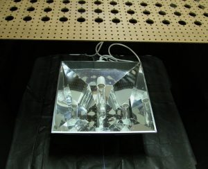
Parabolic reflectors are shaped like a section of a parabola and have one focal point. When the lamp is placed at this focus, the rays of light reflect in a parallel fashion. These types of reflectors are found in the back of regular floodlights, for example car headlights or the kind used to typically light a driveway. For aquarium applications the typical reflectors sold as parabolic reflectors are not completely enclosed parabolic reflectors, but primarily a 2-D swept section of a parabola approximated by bending sheet metal into planar segments. The Spiderlight and the two PFO reflectors are examples of parabolic reflectors. To create a 3-D shape, a faceted construction is used to create a closed parabolic shape in 3-D, e.g. Diamond Light’s Luminarc III reflector.
Positioning of the Lamp
Positioning of the lamp within a reflector has a critical effect on light distribution. Particularly in reflectors that utilize facets in three dimensions (e.g. Diamond Light), positioning a lamp’s inner envelope out of the intended focus will cause a reduction in peak intensity and the symmetry of light output. In reflectors that utilize 2-D sections, positioning of a lamp within the reflector is not as critical. Most importantly however, is positioning the lamp the proper vertical distance away from the reflector. This distance determines whether the lamp is positioned at the reflector’s focus. All reflectors utilizing complex geometry to achieve optimal dispersion are designed with the lamp mounted a specific distance away from the reflector, at the focus of the reflector’s geometry. If lamps are not supplied with mogul bases and standoffs, as is often the case, it will be nearly impossible to achieve an ideal distribution of light output as one does not know the precise focus point that the manufacturer used when designing the reflector.
Reflector Testing
For any reflector we are primarily concerned with two qualities – 1) distribution of light over a specified area, and 2) intensities achieved over a specified area. Clearly, the intensity will be a function of the lamp/ballast combination used; however, the distribution should not change significantly for a different lamp/ballast combination provided the lamp geometry is similar. Wherever possible, the same lamp/ballast combination was used. Table 1 lists the reflectors tested and the ballast and lamp combinations used.
In this article we cover the following popular mogul reflectors:
- PFO Lighting – Parallel Reflector
- PFO Lighting – Perpendicular Reflector
- Digital Oceans – Spider Light
- Diamond Lights – Lumen Arc III
- Synthetic Sun
| Reflector | Ballast used | Lamp used |
|---|---|---|
| PFO Lighting – Parallel Reflector | PFO 400W Magnetic Ballast | 400W Ushio 10000K |
| PFO Lighting – Perpendicular Reflector | ||
| Digital Oceans – Spider Light | ||
| Diamond Light – LA3 | ||
| Synthetic Sun |
Description Of The Test Setup
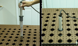
A 3’X 3’ grid with a spacing of 3” in X and Y direction was created using a peg board (fig. 3). These 169 (13X13) points were used to collect data on this grid with (0,0) representing the center of the grid. A right hand coordinate system was used to designate the points on the grid, with the longitudinal axis of the lamp defining the Y-axis. Each reflector was centered on this grid, so that the center of the reflector was aligned with the (0,0) position on the grid. Note that the lamp center was not explicitly centered with the grid. This is inline with how reflectors are typically used in practice, where the reflector position is fixed within a canopy. This grid was mounted on top of a 4’ X 4’ tub, lined with black cardboard paper to eliminate any external light and stray reflections from interfering with the experiment. This inverted setup was chosen to make it easy to position the sensor and thus, data collection was more efficient. A special attachment was made to house the sensor. The collar on this attachment allowed for the sensor to be placed at a specific distance from the lamp, and to maintain the sensor in the vertical position (figure 4). The collar also allows the sensor to be placed at the center of the holes of the grid which correspond to the points at which data is collected. Light intensity readings were taken at distances of 6”, 9” and 12” from the center of the lamp. This distance was maintained by adjusting the length of the pipe holding the sensor. Data at each position was collected using a LICOR 1000 data logger and a LI-192SA underwater cosine corrected sensor calibrated for both air and water.
Data Collection
For each of the above combinations listed in Table 1, data was collected at the 169 grid points and recorded, at a distance of 6”, 9” and 12” from the center of the light source. Each set of complete readings for every reflector took between 4.5-5 hrs.
The data was imported into Microsoft Excel for analysis and the data was plotted in a manner that would be useful for evaluation. For each set of reflectors, three plots were generated:
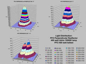
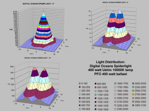
- A 3-D surface plot showing the actual PAR values recorded.
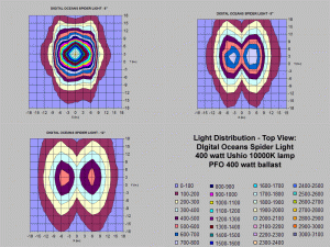
- A contour plot viewing the surface from the top showing the distribution.
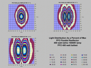
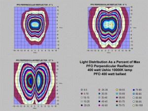
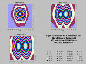
- A plot showing the light distribution as a percent of the maximum recorded value for each of the distances from the lamp. This plot makes the data independent of the lamp, and should stay pretty much the same for different lamp/ballast combinations using the same reflector, and with similar lamp geometry. This would allow us to extrapolate the data for different lamps.
It should be noted here that the light emanating from the reflectors is very different from natural sunlight. Since the sun is so far away from the earth, the intensity at all measured points on a small surface would be identical. This distance is not so for the MH lamps used. These are point sources of light and when placed in a reflector the light emanates in a cone with intensity gradually decreasing as we move away from the central axis of the cone and with increasing distance from the source. For all practical purposes, the intensity as a single measure is not a sufficient measure of the quality of the reflector. What may be a better measure for our use is the amount of area coverage at a given intensity or greater and the shape of this area. The general shape of the area will determine how the light is spread in that area and can be used to determine the rock layout in the tank, or placement of corals in the tank, or even to match the reflector to the tank shape. Also, the summation of light that is incident upon the reflector within a specified area can be compared between one reflector and another. Tables and plots that represent this value for each reflector are presented at the end of this article.
As a practical guide this data can be used in several ways:
- Given the placement of the reflector in the hood it can be used to determine the placement of the corals and rockwork in the tank.
- The impact of raising or lowering the light fixture can be determined with respect to maximum intensity and area coverage at a given intensity.
- Given the shape of the tank and the rock layout, the reflector’s light distribution pattern can be used to select the proper reflector geometry for the tank and the positioning of the reflector within the hood.
- To place corals within the tank if the general light requirements are known.
Reflector Test Data and Analysis
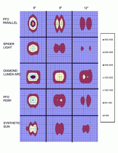
In the following sections, the results of the test data are presented. The data is presented in a form that can be easily interpreted by the reader, and is quite self explanatory. Hence we only discuss some salient points for the reflectors under consideration. When using the data to make comparison, there are several elements that must be taken into consideration especially since there are basic trade offs in any reflector design – intensity vs. spread. Things to look for in the data are the basic shape of the light distribution, the amount of area coverage for a given level of light intensity, peak intensity values, and rate of change from the peak to the outer areas. So when evaluating the reflectors, one needs to look at multiple performance criteria and select one that meets the needs of the tank, the tank layout, space constraints, and budget constraints.
1. PFO Parallel Reflector
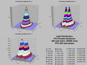
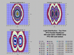
This reflector is manufactured by PFO Lighting. (www.pfolighting.com). The figures 7, 8, and 9 show the results for the PFO Parallel Reflector data
From these charts one can clearly see that the PFO parallel reflector has an elliptical shaped light distribution. It achieves peak intensity at the center, and the intensity drops off as we move away from the center. Peak intensity achieved at 6” is between 3000-3100 μmol/sec/m2, well above the recorded noon time values of 2,000 μmol/sec/m2. However, it is important to note that this peak value occurs over a very small area. At a distance of 6” parallel to the lamp, the intensity drops off to about 20-25% of the maximum.
At a distance of 9” there is an interesting shift in the distribution of the light. The reflected light has created two virtual images of the lamp creating two peaks with the iso-illumination bands forming concentric to them. The basic shape is still elliptical. So when placing corals on a flat rock equidistant from the lamp and high enough in the tank it is quite likely that they may receive different light based on the position with respect to the two peak spots. A coral that ends up getting placed within the valley in the light distribution will receive less light than ones to the side of it along the lamp axis. As you can see from this, even if corals are placed at the same height they do not necessarily get the same amount of light. This is not necessarily bad, but points out the benefits of knowing the lighting distribution pattern.
2. PFO Perpendicular Reflector (Optimal Reflector)
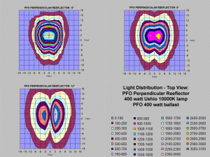
The figures 10, 11, and 12 show the results for the PFO Perpendicular Reflector data
The PFO Perpendicular Reflector has an elliptical spread very similar to the Parallel Reflector. However, in this case the spread is much broader in the x-direction, the direction perpendicular to the long axis of the lamp within the reflector. Peak intensity occurs at 6” and is between 2000-2100 μmol/sec/m2; this value is 1000 units less than that recorded for the Parallel Reflector. At a distance of 9”, the two distinct peaks that were recorded for the Parallel Reflector have not occurred with the Perpendicular Reflector. However, there is a partial split of values at peak intensity, hinting that an intensity split likely occurs at distances slightly beyond 9” from the lamp. Lastly, at 12” from the lamp, a noticeable asymmetrical shape to the curve exists, showing more light on the positive side of the x-axis. While we did not run experiments to determine precisely what causes this effect, we believe it to be a shadow caused by the bar holding the envelope within the outer globe of the metal halide lamp.
3) Digital Oceans SpiderLight
The figures 13, 14 and 15 show the results from the SpiderLight reflector data.
The results from Digital Oceans’ SpiderLight reflector are similar at first glance to those found for PFO’s Perpendicular Reflector, however, there are some differences. While this reflector is similar in design to the PFO Parallel Reflector the light output behaves more like the PFO Parallel Reflector. The SpiderLight reached a peak that was similar to that reached by the PFO Perpendicular Reflector, between 2000-2100 μmol/sec/m2. At 9” the SpiderLight reflector is now showing a noticeable bi-peak distribution similar to that found on the PFO Parallel Reflector at 9” and beyond. Once again, we found an asymmetrical distribution at 12” from the lamp and because we held the bar’s alignment constant throughout testing, this distribution further supports the theory that the bar may be causing a shadow.
4) Diamond Light – Lumen Arc III
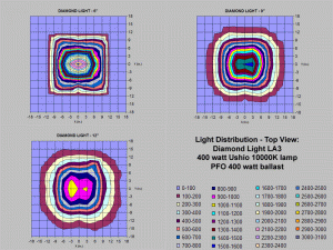
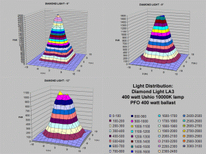
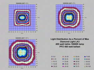
The figures 16, 17 and 18 show the results from the Diamond Light reflector data.
Of all the reflectors tested, the Diamond Light was the most unique. This reflector uses multiple pieces of polished aluminum to create a reflector with twelve individual facets. This multifaceted design dispersed light from the 400 watt lamp very evenly. Also, positioning of the lamp within the reflector is adjustable. This adjustability allows the user to position the inner envelope of the metal halide lamp directly in the center of the reflector, amounting to the most symmetrical spread of any reflector analyzed during this study. The Diamond Light reflector obtained a peak intensity of 2400-2500 μmol/sec/m2. This reflector may not be suitable for everyone, given its rather large size.
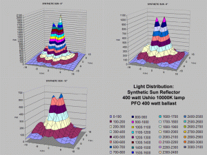
5) Synthetic Sun
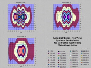
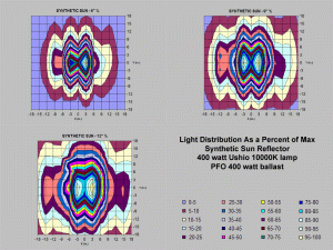
The Synthetic Sun reflector is sold by Champion Lighting, and does not include the mogul socket. The figures 19, 20 and 21 show the results from the Synthetic Sun reflector data.
The Synthetic Sun reflector achieved a similar peak output to the two reflectors already discussed, 1900-2000 μmol/sec/m2, but had other unique attributes. This reflector created as many as four peaks even at a distance of only 6”. This reflector design seems to be aimed at spreading the light out over a larger area.
Comparison of the Reflectors
Acknowledging the fact that the comparison of reflectors should be performed with one’s own objective function and constraints, we define a few objective measures of performance to compare the reflectors based purely on performance measures. We are interested in the total light from the reflector reaching the tank surface, the area of coverage at a given intensity, and the implications of the mounting height of the lamp above the water surface.
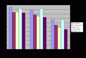
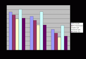
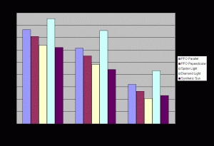
To compare the reflector’s ability to direct light to a specified area, and the change in the amount of light reaching the tank, we created an index (Total Incident PAR) by adding all the discrete measured PAR values over a given surface area. Please note that this is not to be taken as an absolute number, and it is only useful for comparative purposes. Table 2 and Fig. 22, 23 and 24 shows a comparison of the different reflectors using this index of Total Incident PAR.
| Reflector | Distance | Light incident 3 X 3 Area | Light incident 2 X 2 Area | Light incident 1 X 1 Area | Maximum PAR |
|---|---|---|---|---|---|
| PFO Parallel | 6” | 47,415 | 44,495 | 33,313 | 3,062 |
| 9” | 42,449 | 37,603 | 23,052 | 1,599 | |
| 12” | 38,238 | 30,702 | 15,962 | 829 | |
| PFOPerpendicular | 6” | 41,810 | 39,179 | 27,456 | 2,070 |
| 9” | 39,213 | 33,212 | 18,871 | 1,066 | |
| 12” | 35,456 | 27,573 | 13,185 | 809 | |
| Spiderlight | 6” | 42,185 | 37,456 | 24,986 | 2,033 |
| 9” | 34,909 | 27,927 | 14,225 | 762 | |
| 12” | 31,904 | 24,100 | 10,261 | 545 | |
| Diamond Light | 6” | 46,143 | 46,099 | 33,542 | 2,450 |
| 9” | 45,317 | 42,782 | 27,432 | 1,538 | |
| 12” | 42,752 | 37,853 | 21,562 | 1,018 | |
| SyntheticSun | 6” | 41,384 | 36,307 | 22,484 | 2,046 |
| 9” | 35,590 | 27,991 | 15,488 | 1,024 | |
| 12” | 31,025 | 22,106 | 11,481 | 662 |
This comparison reveals some interesting results. It can be seen that the Diamond Light reflector achieves the highest total incident light compared to all other reflectors at all areas measured and distances taken from the lamp. Also, all reflectors lose light incident on the surface as one goes from 6” distance from the lamp to 12”.
The percent loss of light as distance from the lamp increases can be used as another measure to evaluate the reflectors ability to keep the light focused as the distance between the lamp/reflector and the water surface is increased. Table 3 presents the results of changing the distance from 6 to 12”.
| 3×3′ Area | 2×2′ Area | 1×1′ Area | |
|---|---|---|---|
| Diamond Light | 7% | 18% | 36% |
| PFO Perpendicular | 15% | 30% | 52% |
| PFO Parallel | 19% | 31% | 52% |
| Spider Light | 24% | 36% | 59% |
| Synthetic Sun | 25% | 39% | 49% |
This means that the Diamond Light reflector loses the least amount of light as one moves farther away from it.
Another measure of reflector performance can be based on the amount of area covered by light intensity greater than some specified value. Say for example the user decides that they are interested in a minimum PAR of 500 μmol/sec/m2, we can then compare the area over which this light intensity can be achieved. The larger the specified area the better the reflector performance for the criteria specified. Fig 25 shows an example the area coverage by the different reflectors when the cut off is specified as 500 μmol/sec/m2. This figure shows graphically the area covered with the light cut off at 500 μmol/sec/m2. (It would be nice to have actually computed this area – if anyone has any software that will allow this computation, please contact me).
Comparison Of A Flat Reflector With White Paint
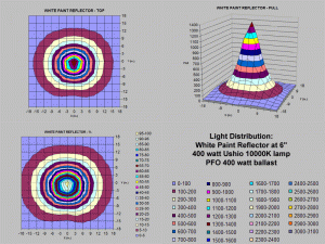
A question that an aquarist may ask is “Why should I even bother having a reflector?” Just painting the inside of the hood white may be enough. To address this question we set the lamp against a 1’ X 1’ piece of wood painted with a flat white paint. The data for this was only collected at one distance – 6”. Figure 26 shows the light distribution for this setup.
The total light incident on the three different areas 3’ X 3’ ft, 2’ X 2’ and 1’ X 1’ at 6” from the lamp using a flat sheet reflector with white paint is shown in the table 4 below. As can be clearly seen from the data, having any of the above mentioned reflectors is better than just having a painted hood.
| Area 3X3 | Area 2X2 | Area 1X1 | Max. PAR | |
|---|---|---|---|---|
| Incident Light | 32895 | 28275 | 17858 | 1387 |
Conclusion
This article presents the data and some analysis of the light distribution of various reflectors used with mogul base lamps, and shows the impact of light distribution and intensity as a function of the reflector. While the data collected is with a 400W 10000K Ushio lamp, the data can be extrapolated to other lamps using the percent plots, as long the lamp geometry is not considerably different. The peak intensity measurement along with the percent plot can be used to extrapolate the light distribution for any lamp/ballast/reflector combination. In a future article, we will present the results for the reflectors used with the double ended lamps.
Acknowledgements
We would like to thank several people whose help made this study possible. They were kind enough to provide us with lamps, reflectors and ballasts for testing: Patrick at PFO Lighting, Brad at Sunlight Supply, Champion Lighting, Shane Graber, Kevin Tompkins, and reefs.org.
References
- Joshi, S. 1998. Spectral Analysis of Metal Halide Lamps Used in the Reef Aquarium Hobby Part 1: New 400-watt Lamps, http://www.animalnetwork.com/fish2/aqfm/1998/nov/features/1/default.asp
- Joshi, S. and Morgan D. 1999. Spectral Analysis of Metal Halide Lamps Used in the Reef Aquarium Hobby Part II: Used 400-watt Lamps http://www.animalnetwork.com/fish2/aqfm/1999/jan/features/2/default.asp
- Joshi, S. and Morgan, D. 1999. Spectral Analysis of Metal Halide Lamps Used in the Reef Aquarium Hobby Part III: New and used 250-watt Lamps http://www.animalnetwork.com/fish2/aqfm/1999/dec/features/2/default.asp
- Joshi, S. and Morgan D., “Spectral Analysis of Metal Halide Lamps – Do Ballasts Make a Difference,” 2001 Annual Marine Fish and Reef USA, Fancy Publications.
- Joshi, S., “Spectral Analysis of Recent Metal Halide Lamps: Part IV– 10000K and 12000K lamps,” 2002 Annual Marine Fish and Reef USA, Fancy Publications.
- Joshi, S. and Marks, Timothy. 2002. Spectral Analysis of Recent Metal Halide Lamps and Ballasts: Part VI, http://www.advancedaquarist.com/2002/10/aafeature
- Joshi, S. and Marks, Timothy. 2002. Spectral Analysis of 150W Double Ended Metal Halide Lamps and Ballasts http://www.advancedaquarist.com/2002/11/aafeature
- Harker, R. “Reflecting on Lighting”, Aquarium Frontiers, Nov 1999. http://www.animalnetwork.com/fish2/aqfm/1999/nov/features/1/default.asp




0 Comments