I'm playing with the design of my sump that will go onto an 80 Gal. (48"L x 18"W x 23"H) Reef tank and wanted to see if anyone had any input on the design.
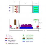
Below you will find a link to the image of the sump. This is not to scale but close.
http://www.calped.com/patrick/sump.jpg
The 80 Gal. display will drain to the sump via (3) 1" or 1.5" drains to the right side of the sump. Going into the 3 bulkheads that will go into the PVC T's that will distribute water over the Distrubution tray which is removable for cleaning. The tray will sit on two small rails that will be Siliconed into the sump about 4" or so down. This idea was taken from a wet/dry that I own made by Sea Life Systems http://www.sealifesystems.com/wetdryinter.html
This tray will also be used to hold polyfilter or some sort of prefilter media. Dimensions of the tray 8" (L) X 12.75" (width of inside of tank) X 4" H.
This will drain to the Skimmer chamber. Water from this chamber will be pumped into the skimmer (possibly an EV-240) and return via the bulkhead and PVC attached at the yellow area (below the tray) but above the water line.
This skimmer chamber will be seperated from the DSB/LR chamber by a height ajustable Plexi divider. This idea came from Sea Life Systems Pro Skimmer/Sump setup http://www.sealifesystems.com/Pro.html
The next divider will be of the same nature so I can adjust water level in the DSB/LR chamber.
Next section will be a set 3 of dividers setup to reduce/eliminate bubbles from getting back into the display. The last divider will be used to hold (3) 3" Media Tubes that will get water flow from a T off the return pump with a gate valve after the T and ball valves for each cylinder. Used as needed. This will also hold any probes that I may add at a later date. This will also have a sponge on exit to eliminate any debris that may try and escape the DBS/LR area. The cylinder idea came from http://www.lifereef.com
The last chamber will hold heaters and anything else that may be needed at a later time ie: Cal. Reator, Chiller, UV etc.
I have included 2 outlets in the last chamber so that I can run 1 pump for return and a 2nd pump for additional circulation or powering other items (ie: Refugium, cal. reactor, UV, Chiller, Media Cylinders, etc.).
I plan on keeping water level 6-7" from the top of the sump tank to accomidate overflow water if power was to ever fail (Likely to happen here in California). I have calculated it to be about 15 gals of over flow if this was to happen, and 6-7" of sump volume works out to be 15.5-16 gals. of space.
Let me know if you find anything that I'm forgetting or anything that might cause problems down the road.


