• Why not take a moment to introduce yourself to our members?

Cresta

Experienced Reefer
Location
Los Angeles
Rating - 0%
0   0   0
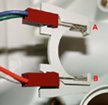
I want to disable the "drip sensors" on my perisaltic feeder pump. After opening the pump unit, I found two sensors located close to where the drip capsule is at. I'm guessing they are photo transistors(?). The sensors face each other with the drip capsule in the middle. The sesors notify the unit if there are actual liquid passing through. Each sensor has two legs. One longer than the other, I'm assuming its like cathode and anode ends on LEDs. Each leg has a wire connected to it...so there are a total of 4 wires. The four wires then connect to the main electronic circuit board.

I don't know if there is an easy way to bypass the sensors (ie. close each pair of wires with resistor?).

Any help is greatly appreciated.
 
A

Anonymous

Guest
Rating - 0%
0   0   0
Very close. One is a LED, while the other is a photodiode. This is not cheap device, so it is best if you call the manufacturer and ask them about hacking it.

If you can't talk to the OEM, then let me comment the following. Depends on the sensing algorithm, you may not be able to just add a bypass to get it to work. This is because some of the mechanism involves the water drip as "light chopper," so the photodiode is expecting a periodic signal while the output of the LED is constant.
 

Cresta

Experienced Reefer
Location
Los Angeles
Rating - 0%
0   0   0
I called the manufacturer and they are not of much help. The rep only knew operating and maintainence instructions.

What you mentioned regarding "chopping signals" makes sense....

Hopfully others have more ideas on this :(
 
A

Anonymous

Guest
Rating - 0%
0   0   0
It is usually more hassle than it worth, but you can always use a IC555 to generate a signal to drive the LED, and use it to confuse the photodiode. It is usually consider a bad taste among electronics hackers to send signal to the photodiode directly (such as the by-pass trick you suggested). So it is better to drive the LED instead.

Your experience with the OEM is not unexpected. Try and see if they have a *real* technical support, or just a bunch of salesmen and marketing folks. Again, don't expect any of them to offer you any advice since modification of the device other than the OEM *WILL* void the warrenty.
 

smlacy

Experienced Reefer
Rating - 0%
0   0   0
Ermin, which brand of pump do you have? I have a FlexiFlow III and have thought about doing the same thing. The first step is to put the photodiode outputs onto an Oscilliscope and see what signals are happening there, then do something as Loule suggested, and synthesize a similar pattern on the LED.

Steve
 
A

Anonymous

Guest
Rating - 0%
0   0   0
You guys are making it way too hard. If you just want to bypass the drip counter, Just bypass it.

Take a piece of black electrical tape and cover the emmiter and/or the reciever.

If the pump stops all together, Take off the tape.

Take the emmiter/reciever unit out and make them face each other (while still plugged in.) but not in the water path. (like folding them back into the case.

One or the other should make the pump act without the sensor.

B
 

smlacy

Experienced Reefer
Rating - 0%
0   0   0
Bingo, these things are more complicated and robust than you think. They're medical "enteral" (in the stomach/intestine) feeding pumps, so they have many safeguards to make sure that there is really something in there, and that its really dripping. I have one now, and the pump will not run without the sensor sensing a valid "drip" whatever that means.

If the sensor is left bare, nothing happens.
If the sensor is covered up, nothing happens.

I'm not sure exactly what other logic happens inbetween there.
 
A

Anonymous

Guest
Rating - 0%
0   0   0
Ahh. so much for the easy route. You're gonna have to find someone with an Oscilloscope and figure out the signal a 'drip' makes. Then reproduce it. (ugh. time to ghetto out a timer chip!)

on the other hand, Why do you want to overide the sensor in the first place?


B
 
A

Anonymous

Guest
Rating - 0%
0   0   0
I don't think a oscilloscope is really a must, since the chopping rate is typically very slow. Maybe able to get around the issue even without a voltmeter. If you just want to fool the photodiode, just sent signal via the LED in reasonable frequence, say, about 2Hz (2 drops per seconds).
 
A

Anonymous

Guest
Rating - 0%
0   0   0
LOULE":11j6jf3q said:
I don't think a oscilloscope is really a must, since the chopping rate is typically very slow. Maybe able to get around the issue even without a voltmeter. If you just want to fool the photodiode, just sent signal via the LED in reasonable frequence, say, about 2Hz (2 drops per seconds).

Good idea, you could also put a trimmer pot on it to adjust the rate.

B
 

Cresta

Experienced Reefer
Location
Los Angeles
Rating - 0%
0   0   0
As smlacy had mentioned, either option stops the pump.

I think I will have to use a trimmer pot instead of a LED. If I enter 10ml/ hr dosing rate on the pump, the sensors will look for "10ml/hr" type of drip. Just adding a LED is very difficult to match it with the required signal. The pot will let me tune it until the signal is matched. But what kind of pot should I use?

How would I attach the pot to the circuit? Pots have 2 wires I think..... there are four wires total on the two sensors.
 
A

Anonymous

Guest
Rating - 0%
0   0   0
Depends on the sensor algorithm, a pot will probably not going to work. If a chopping signal is expected from the photodiode, it is not possible to duplicate that with a pot. With IC555, you can match any any reasonable signal. You can use a pot with the IC555 to change the frequency of the signal if you want.

Use IC555 or other signal generator to drive the LED (two of the four wires on the drip sensing module), and leave the photodiode wires the way it used to.
 

Cresta

Experienced Reefer
Location
Los Angeles
Rating - 0%
0   0   0
Several pictures of the sensor unit.
 

Attachments

  • sensor.jpg
    sensor.jpg
    49.1 KB · Views: 1,666
  • photodiode.jpg
    photodiode.jpg
    8.7 KB · Views: 1,668

Sponsor Reefs

We're a FREE website, and we exist because of hobbyists like YOU who help us run this community.

Click here to sponsor $10:


Top