• Why not take a moment to introduce yourself to our members?

hfmann

Advanced Reefer
Rating - 0%
0   0   0
Hi Brian,

After getting back from vacation, I'm wrapping up the assembly of my reactor. While finishing it, I'm also constructing the KW reactor and am going to use an O ring instead of gasket. Would like your opinion/comments on the following o ring methodology.

After examining a commercial skimmer I've got that uses an o-ring, I've decided to glue the acrylic tube to the top flange as we did in the reactor class. But, instead of flush trimming to the inside of the tube, I'll leave a 1/4" lip inside the tube. Then I'll rout a 1/8" deep x 1/4" wide rabbet on the top of this lip. The o-ring will fit into this rabbet. You previously cautioned me about a rabbet weakening the product some. I take it the manufacturer of the skimmer did it this way to avoid the weakeness you were referring to.

What do you think? Does this make sense? Any words of wisdom or other tips?

Thanks.
Hal
 

fergy

Advanced Reefer
Rating - 0%
0   0   0
actually, it will still weaken it a bit, but not alot.

Here's why that manufacturer did it like that: They didn't want to have to do a tool change on the CNC router they were using, if it's who I think it was. He used a flat-nose cutter to machine all of the plastic. Also, he didn't want to spend the time to flush trim the inside afterward.

Ideally, you'd machine a round groove in the face of the flange, that the oring sets into. That groove would be pretty close to the bolts, because that's where the pressure is. The flat groove is a little harder to seal than the round groove, and more likely to cause a crack. You want to avoid having your groove right over where the tube is, becuase that's a stress point when you tighten the bolts, and if it's got a square-bottomed channel machined opposite it, the plastic will want to crack at the bottom corners of that channel. Another reason not to make them square.

It's up to you, how you do it. Before you cut out the center of the flange, you can use a hole in the exact center as a pivot point for machining that groove.

BRIAN
_________________
Entourage Forum
 

hfmann

Advanced Reefer
Rating - 0%
0   0   0
Brian,

Thanks so much for the fast and very thorough reply. It gives me much to think about. I was going to do some of this machining tonight, so I especially appreciate that you got the info to me in time to STOP and rethink this. Everything you said makes perfect sense :) .

It's up to you, how you do it. Before you cut out the center of the flange, you can use a hole in the exact center as a pivot point for machining that groove.

Great idea. Now that I'm thinking more about it, I want to do the outer groove strategy. However, I already made a big rough hole in the middle of the flange so i wouldn't have any problems getting my flush trim bit started. So I'll have to figure out how to do this. Maybe use my pin router setup. Back to the instruction manual :lol: thanks.

I will keep working on the calc reactor assembly tonight though. Tom at inland didn't ship my pump and arm until today, so I've got time to keep to do it right.

Take care,
Hal
 

hfmann

Advanced Reefer
Rating - 0%
0   0   0
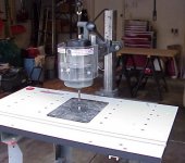
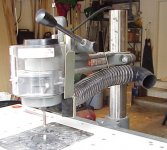
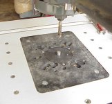
It's a setup where the router fits into an overarm cradle contraption. Came as part of my router table. I've never used it before. Tonight I pulled out the instruction manual and am currently aligning and adjusting the table to be perpendicular front and back / side to side to the router bit. Low and behold it's got instructions on how to do mass production! And furthermore, the arm holds a dust collection hookup that works for the under table router setup too. Wish I had known that before :lol: .

I'll let you know how it works out.

Thanks again for the help.
Hal
 

agiacosa

Experienced Reefer
Rating - 0%
0   0   0
Hal,

Can you let us know what brand router table you have and how the mass production thing works? I'm going to make a couple of reactors for family members and don't want to take on the expense of having a CNC router cut up the pieces.

Thanks.

Art
 

hfmann

Advanced Reefer
Rating - 0%
0   0   0
Hi Art,

It's a stand alone Shopsmith system. By that I mean it isn't the one that runs off of the mutli purpose Shopsmith Mark V unit. I don't think they market the same router configuration anymore.

As far as the mass production setup goes, the manual spends a total of 4 pages talking about it. Not much detail. Nonetheless, the basic premise is just using templates to duplicate the pieces.

Sorry, probably not much help to you, but it seems to me that the templates we used in the class would work great for making a limited number of units. I'm going to make some extra copies of the templates because I see that I'm already starting to chew up the originals. I won't be making multiple reactors, but the templates we got seem like they'd be good for a lot of different projects.

I'll try and post a picture of my router table / pin router over the weekend.

Take care,
Hal
 

hfmann

Advanced Reefer
Rating - 0%
0   0   0
Brian,

I just had a mind numbing thought that stopped me dead in my tracks.

Ideally, you'd machine a round groove in the face of the flange, that the oring sets into. That groove would be pretty close to the bolts, because that's where the pressure is.

Doesn't this create a small space between the top of the flange and the lid that becomes filled with fluid spilling over from the top of the tube? In theory the o-ring (3/16" diameter buna cord in a 1/8" deep groove) would compress but still leave a some distance between these two pieces? The other manufacturer's method of having the o-ring on a lip inside the edge of the tube keeps the fluid entirely within that cylinder.

I was planning on machining this first thing in the morning but am now having 2nd and 3rd thoughts. What are your thoughts?

(I'm probably thinking too much about this, but really want the first product to work. Takes too much time to make another one or try and salvage the first one.)

Thanks,
Hal
 

fergy

Advanced Reefer
Rating - 0%
0   0   0
No, the outlet fitting extends below the rim. Remember, it extends a bit through the lid. So, in essence, there is an air gap at the top of the reactor.

Also, when i refill my reactor, I actually remove the outlet side of the bubble counter (the hose) and tilt it downward into a bowl or similar, to drain a few inches of water out of the reactor. The bubble counter will stay primed, and you need to remember to turn off the water feed to it.

Make sense?

BRIAN
_________________
Honda VT250F
 

agiacosa

Experienced Reefer
Rating - 0%
0   0   0
So, is it 1/4" diameter or 3/16"? At 6.5" the O-ring is close to the screws.

Also, I didn't follow your last comment Fergy. I too thought I would have spillage of water up to the O-ring especially with the pressure build up in the reactor.

Thanks.

Art
 

hfmann

Advanced Reefer
Rating - 0%
0   0   0
Ok Brian,

What you say does make sense.

However, the unit I'm using this o-ring configuration for is a KW reactor, so air in the reactor chamber is an issue, right? I was thinking about cutting off the part of the fitting that extends into the chamber just to eliminate even more air. I guess with the shortened fitting, the air would be eliminated under either o-ring location.

When refilling your reactor, I take it you're tilting the unit, removing some water, in order to make remove for the new media.

Off to the lumber yard to get some MDF. Need to make some more templates and got to play with this pin router setup before I start on the actual pieces.

Art as I understand it, the recommended o-ring size is 3/16 or 1/4 as long as the groove is just a little bigger. I'm using 3/16 with a 1/4 groove (6 1/2" OD) and that looks like it'll put the o-ring within 1/4 of the bolts.

As always, thanks for the very quick responses.
 

fergy

Advanced Reefer
Rating - 0%
0   0   0
Hfman:

you've got it. That's about perfect for an oring.

The air in the chamber won't be a problem for long. It will react at first, then no longer affect the kalk.

When refilling, I do not tip the reactor. I drain water out of it by disconnecting the hose that feeds the pump from the bubble counter, and then tipping that end downward into a bowl or similar until the water level in the reactor drops.

Art:

I tend to use a 1/4" oring in a 1/4" channel, but 3/16" works just as well. The buna cord stock that I use is undersized just slightly. !/4" sticks into the groove a little better, but it makes a larger gap between the pieces. It kinda depends on what I'm making.

There's no pressure buildup in the reactor because the pressure escapes from the top of the reactor.

BRIAN
_________________
Mercedes Benz O309
 

agiacosa

Experienced Reefer
Rating - 0%
0   0   0
Fergy,

Thanks.

If pressure escapes through the top of the reactor, why does the MTC model have a pressure guage on top of the reactor tube? Is it because it is a two chamber reactor?

Thanks.

Art
 

hfmann

Advanced Reefer
Rating - 0%
0   0   0
Here's some pix of the router table with the overarm router setup. I know I don't / won't need the flush bit shown when using the pin setup. Just using it while doing the alignment.

Hal
 

Attachments

  • routertable.jpg
    routertable.jpg
    51.8 KB · Views: 130
  • overarmrouterwdust.jpg
    overarmrouterwdust.jpg
    59.1 KB · Views: 127
  • tableinsertpin.jpg
    tableinsertpin.jpg
    55.8 KB · Views: 128

fergy

Advanced Reefer
Rating - 0%
0   0   0
Hal:

Have you figured out how to use that thing to machine the grooves to socket tubes yet? Pretty much the same as for the oring...just be careful.

Art:

I don't remember exactly where the outlet is on the ProCal, but I believe their reactors are set up in such a way as to be pressurized just slightly. I also think there's a pressure-relief valve built in. Remember, you're using compressed gas, and the reactor can be pressurized just slightly. I don't like to do it, but it does increase the saturation of CO2 in the water, and can speed up the reaction. I choose to go the other direction, and just force more CO2 and water into the reactor. Their units are good, and they were one of the first, and are still probably the most-advanced ones out there. But, I think most of it is overkill for our purposes.

BRIAN
_________________
Algerian Forum
 

hfmann

Advanced Reefer
Rating - 0%
0   0   0
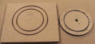
I made a template with two grooves in it for the pin to follow. One to cut the outside diameter of the flange, the other to cut the groove for the o-ring. I guess I'll need to add a third if I want to "socket" tubes. How do you go about gluing a tube in a channel. I wouldn't guess you'd use the wire pin method?

Here's a poor picture of the template and the resulting acrylic piece (flange for my KW reactor).
 

Attachments

  • mvc-795f.jpg
    mvc-795f.jpg
    44.1 KB · Views: 122

fergy

Advanced Reefer
Rating - 0%
0   0   0
Yup, that's perfect. The channel for the tube is similar, but needs to be JUST over .25" because of the poor tolerances in tube wall. There needs to be a little slop in there. Then you carefully fill that channel with #40, and set the tube into it, rock it just a little to seat it in there, and you're good to go. The squeezeout from the joint will be clear, and will shrink as it dries, forming a fillet around the tube.

BRIAN
_________________
chocolate chunk
 

hfmann

Advanced Reefer
Rating - 0%
0   0   0
Cool, How deep a channel to make for the tube? But why put the tube in a channel if we just flush trim to the inside wall anyway?

I'm laughing at myself for making making templates since I'm not producing more than what I'll use myself? Guess I'm want to see if I can do it. And maybe they're be other projects to use them on. Skimmer? :)

Hal
 

fergy

Advanced Reefer
Rating - 0%
0   0   0
Yep.

I make the groove .05 deep. Let's see you match that.

Here's another tip for you...make another groove on that template, for the ID of the flange. Make it 5.35" in diameter. That way, you have now removed most of that inside material, and you only shave when you flush trim. Make sense?

Yes, you remove the inside of that channel when you trim it. BUT, if that inside side of the channel isn't there, the #40 runs out of the channel. Also, it makes it much faster to center the tube perfectly on the flange. And no tape blocks.

Also, have you realized you can use the pin router for the keyholes yet? No drilling...but you'll need a regular spiral bit

BRIAN
_________________
economic stimulus plan
 

hfmann

Advanced Reefer
Rating - 0%
0   0   0
I make the groove .05 deep. Let's see you match that.
UNCLE! But that solves my image of mixing gallons of #40 to fill that channel :lol:

Here's another tip for you...make another groove on that template, for the ID of the flange. Make it 5.35" in diameter. That way, you have now removed most of that inside material, and you only shave when you flush trim. Make sense?
Wow! I like that idea. I'll still have to convert my table back to under table routing for the flush trim. I don't think I'd feel comfortable doing this with a handheld router.

Also, have you realized you can use the pin router for the keyholes yet? No drilling...but you'll need a regular spiral bit
Yes. I was going to put the keyholes in the template today but ran out of time. Actually I'm using threaded holes in the flange and keyholes on the lid, so my lid template will have the keyholes in it. Wait....I think I can make one template that'll have everything in it for both the flange and the lid. Just gotta make sure I use the right pin channels on the right piece on the right side (e.g. o-ring groove goes on top of flange, tube channel goes on bottom of flange, etc.).

The regular spiral bit still needs to be an acrylic bit, right, and down spiral instead of up? Or do I need up to get the chips out of the way?
 

Sponsor Reefs

We're a FREE website, and we exist because of hobbyists like YOU who help us run this community.

Click here to sponsor $10:


Top