

Has anyone sucessfully rewired the odyssea light for more plugs. I got this odyssea light cheap however there is one plug with three switches (moonlights, actinics, daylight) is it possible to put each switch on its own plug.......if so can someone talk me through it.....I dont want to distroy a perfectly good light.

You are using an out of date browser. It may not display this or other websites correctly.
You should upgrade or use an alternative browser.
You should upgrade or use an alternative browser.
rewire the odyssea light
- Thread starter zev
- Start date
I would think you could set up a electronic timed swich of some sort just by cutting the hot lead to the light swiches, and have the timer turn them on and off. just look for something that just opens and closes the swich nothing more , I would hate to even try thru the ballasts cuse then it could all be run off of one, and then all the extra wire breaks and so on, that could ground out or not be connected.....yeah I think this would be your safest route.
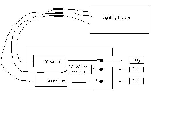
Well not having actually seen the inside of the ballast assembly I'm going to make a guess to what it's made of. But I'd guess that the three wires that run from the light assembling go into the "box" inside this "box" there is a metal halide ballast, an electronic ballast (for PC bulbs), and I'd guess a DC/AC converter for the moonlights (assuming they use LEDs) then all of those are are connected to a shared plug, and being as each device draws whatever power it needs.
Now if this is the case, it would simply be a matter of opening up the "box" and snipping the main wire where they connect to all the devices (black dot) , then you can run an individual plug from each device without any issues at all.
Now if this is the case, it would simply be a matter of opening up the "box" and snipping the main wire where they connect to all the devices (black dot) , then you can run an individual plug from each device without any issues at all.
Attachments

I had the same problem. Took the box apart, carefully traced all of the wires from the PC ballast to the power cord, cut the PC ballast's wires off of the original power cord, then wired in a new one with crimp connectors.
Mind you, I've no previous electrical experience.
I'll say this much -- my ballast box is a tangled mess of wires. I had no idea it would require that many wires. I broke it down into "wires running to/from the PC ballasts" and "wires running from/to the MH ballast." You'd have to make a third set for the moonligt circuit. Then I just followed them to thier ends, and tapped the wires running to the white lead at the shared fuse. Since all the wires connected to the power's white lead also connected to the fuse, that was the likely place to tap. Then matched up what was connected to the green, snipped it, and connected up to the new green lead. The ground just got run to the same spot as the existing ground.
I could probably talk you through it (I'm kicking myself that I didn't take pictures...)
Let me know if you still need help!
I just dealt with the same problem myself, I approached it in a different way though. Instead of wiring an extra plug for each switch, I spliced in timers in series for each circuit. This left only one plug for the entire ballast to plug in and left me with timer control of each lighting circuit independant from each other.
Here's the list of parts (from any hardware store): 16 gauge stranded wire(easier to work with in the small space), 6 wire nuts for 16 gauge wire, and 3 Intermatic wall switch timers.
WARNING - unplug the ballast box before doing any of this work.
First, prewire (for series as per the timer directions) and mount the timers in a seperate box. Be sure to label each set of wires for it's respective switch.
Second, unplug and open the ballast. Locate the white wire coming from the plug and follow it to the fuse. Coming out of the fuse will be two black wires.
Follow one, it will go to #9 on the terminal board. This will be the circuit for the MH, cut this wire (not too close to the terminal board) and splice in the timer using the wire nuts. One splice from the ballast box to the timer, another from the timer to the ballast box. It's just like repacing a wall switch.
Follow the other and you will come to a splice with two more wires.
Follow one of these to #5 on the terminal board. This is the circuit for the CF. Cut this wire and splice in the timer as above.
Follow the other one to #6 on the terminal board. This is for the moonlight. Again cut and splice in the timer as above.
You're now wired! Close up the box. I ran my wiring through the side vents of the case to prevent pinching or crimping any wires while closing up the box. This has been working very well for me and I hope it helps others.
Some things to note: I never saw any markings on the fixture or ballast for UL certification, so definitely have this plugged in to a GFI outlet. I chased each wire and drew out the schematic, but I'm afraid that I'm probably the only one that could decipher it. If anyone has any questions, feel free to ask and I'll answer the best I can.
I rewired mine about two days after receiving it.
I simply used a multimeter (on the continuity setting) to find which switches went to what wires on the opposite end, and wired them to individual plugs.
Took about thirty minutes total.
I wired the first ballast (Actinics) with the fans, the second ballast (12KKs) by themself, and then the 6V inverter by itself........three plugs, three timers.
Works pretty well. I do have a lot of noise from the fans...maybe I'll remedy that tomorrow......I'm also looking at relamping them very soon.
Robbie
Sponsor Reefs
We're a FREE website, and we exist because of hobbyists like YOU who help us run this community.
Click here to sponsor $10: