• Why not take a moment to introduce yourself to our members?

Rating - 99.1%
225   2   0
I have put together couple pics and simple instructions for anyone interested in making their own LED SPY Light.

As we know, most marine live cannot see in red light while we human beings can. Why not build a permanent spy light if it's not too hard to do?

First I will show you the bare minimal you can use to finished, then when time allows I will also discuss how to improve it. If more time is available I may go into more advance topic of voltage, current drivers and flashing technique

Initial Equipment:

1)Soldering iron and solder of course
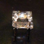
2)6 red LED
3)some wires (almost any gauge goes/pick some junk equipment and pull the wires out)
4)adhesive tape (low tag masking tape is preferred)
5)12V VDC ac adapter (you can get it from Radio Shack or even one of your USB computer hard drive power supply(most come in 12VDC-you can read the label to find out). Most current AC to DC adapters now come with center positive and the outside sleeve negative. Check the diagram on the label to make sure


Some Basics:
LED are diodes and had polarity therefore power must be supplied accordingly.
LEDs of different colors and different brands and models are not born equal. It's best to get the specs where you buy them but sometimes estimates are good enough if efficiency of light is your primarily concern. Red LEDs in general run at 2-2.2V, so if you don't know what voltage of the LEDs you have at hand a 2V is safe to start with.
LED runs optimally at a certain voltage, therefore without a spec you hardly optimize the output
LED will burn out if too high a voltage is applied.
LEDs can be connected in parallel and in series but the voltage of the power supply must be adjusted to proper level.
Saltwater vapor is erosive to metal, therefore all metallic joints should be sealed with heat resistant silicon or glue.

I am using a 12VDC adapter so if I connect the LEDs in series then 2V+2V+2V+2V+2V+2V = 12V. Each LED will receive 2V and should fall within the safe limits of usage.
 
Last edited:
Rating - 99.1%
225   2   0
Reserved 1

Some stuff that you may need to build the project:
1)LED shown
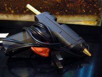
2)Heat Glue Gun if you don't know what it looks like
 

Attachments

  • High Flux LED P1040602 copy.jpg
    High Flux LED P1040602 copy.jpg
    332.7 KB · Views: 699
  • Heat Glue Gun P1040611 copy.jpg
    Heat Glue Gun P1040611 copy.jpg
    355.5 KB · Views: 704
Last edited:
Rating - 99.1%
225   2   0
Reserved 2

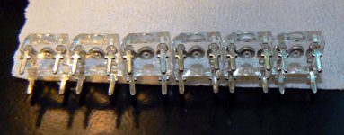
1)Align the LEDs along a straight edge
Tape the other side of the LED so that the legs are still exposed for later soldering

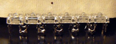
2)LEDs connected by solder alone without help of any wires. Then apply heat glue on the back of the LED to strengthen the structure. Use water resistant and heat resistant glue is a better choice. I used heat glue only because they are around next to me and I know, from experience, this final product would not produce strong heat.

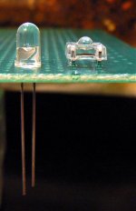
3)Connect wires to the power supply. try to follow color coding custom. Gold, red and a wire with strong marking printed as positive and silver, white, black and plain without markings wire as negative. Note: the cut corner of the LED means negative. Check the LED tester diagram when I finish posting. If you are using the more common 3mm and 5mm LED the shorter leg is the negative.
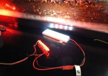
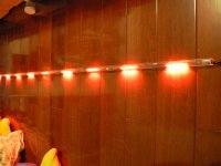
Pic shown finished product for fresh water application, make sure if you are using it for SW, all metal must be sealed!!!

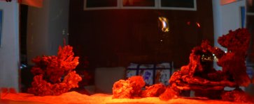
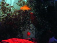
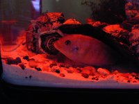
4)Spy light in action in a saltware tank

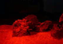
5)Closeup of spy in action. I will try to take a pic with some animal moving around when it happens.
 

Attachments

  • Line LED with Masking Tape P1040603 copy.jpg
    Line LED with Masking Tape P1040603 copy.jpg
    327 KB · Views: 683
  • LED Connected With Soldering Iron P1040606 copy.jpg
    LED Connected With Soldering Iron P1040606 copy.jpg
    326.1 KB · Views: 680
  • Red vs White LED P1040624 copy.jpg
    Red vs White LED P1040624 copy.jpg
    490.2 KB · Views: 668
  • FTS Night Spy Light In Action 1 P1040592 copy.jpg
    FTS Night Spy Light In Action 1 P1040592 copy.jpg
    258.3 KB · Views: 666
  • Close Up Spy Light In Acion 1 P1040593 copy.jpg
    Close Up Spy Light In Acion 1 P1040593 copy.jpg
    393.8 KB · Views: 663
Last edited:
Rating - 99.1%
225   2   0
Reserved 3

Discussion for Improvement:

Now if you found that you are into fooling around with electronics, here some more equipment you should get:

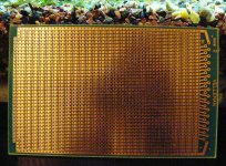
1)PCB: Make your work look more professional and life much easier and finish the project much faster

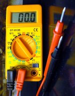
2)Multi Meter: You will use it in too many occasions

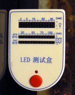
3)LED Tester: If you do a large amount of LEDs and/or need to change designs frequently-you need it

4)Connectors for the adapters: Make all your end products plug and play

5)Switches (2 way rocker is a good choice): You can turn the white light on and RED light off simultaneously and vice versa. So, in the day, white is on and red is off while at night, red is on white is off.

6)Resistors: You will find a bunch of different resistors will become handy. Couple pots will make optimal design easier. You may also want to add a pot to dim the light in actual use. In this example, you may improve the performance of the light by removing 1 LED and adding a proper resistor to it so that it runs at the optimal of this particular LED. To determine the proper value of the resistor, you MUST have the spec from the manufacturer. LED resistor calculator can be found in the web too easily. Also connecting a 1 ohm resistor
in series is always helpful in design and debug phase.
7)Glue: It's also good to use fast setting glue than the slow setting one like ZAP or IC Glue gel commonly use for your frags. Also make you realize that silicone is not real consider a glue but more as a sealant. Finally. the heat glue I was using in this example is not to be used inadvertently, because since it heat melting, it set to melt in low level of heat which render it not suitable higher power design. If you ever plans to enclose the LED in a water proof box, replace it with other glue.

Note: If you have some old but working cell phone charger, post a CLEAR pic of the label in your reply so that I can tell you what it means. I am going to write another example of using an old cell phone charger that is not 12V. You will need to know more about electronics than the "almost fool-proof" version above.

ENJOY and hope you find this article useful.
 

Attachments

  • PCB Board P1040618 copy.jpg
    PCB Board P1040618 copy.jpg
    537 KB · Views: 654
  • Advantage of PCB P1040623 copy.jpg
    Advantage of PCB P1040623 copy.jpg
    35.5 KB · Views: 639
  • Multi Meter P1040616 copy.jpg
    Multi Meter P1040616 copy.jpg
    369.1 KB · Views: 646
  • LED Testor P1040615 copy.jpg
    LED Testor P1040615 copy.jpg
    352.2 KB · Views: 637
Last edited:

bad coffee

Inept at life.
Rating - 100%
27   0   0
Nice. Wingo, do you have specs on those 4 post led's? I'm diggin them.

I'm planing to make exactly what you have, but want one strip blue and one red. Blue for regular night lights, and red for night viewing.

B
 
Rating - 99.1%
225   2   0
Nice. Wingo, do you have specs on those 4 post led's? I'm diggin them.

I'm planing to make exactly what you have, but want one strip blue and one red. Blue for regular night lights, and red for night viewing.

B

I don't have the spec for this particular red ones I use but the others offered by the same manufacturers are 624 nm, 2.2 vF typical, 2.6vf Max(short term) 2200~3600mlm(1100~1800mcd) @50mA, 70-80 degree

I think I do have the spec for the blue ones I have-will check where they are. Send an email so that I can attach the pdf to you if found.
 

boozeman

Junior Member
Location
queens
Rating - 100%
12   0   0
very nice DIY !!
been some years, but I remember many lighting stores on Bowery street would sell LED arays like that in various sizes that you could just soder to a power source.
 

Sponsor Reefs

We're a FREE website, and we exist because of hobbyists like YOU who help us run this community.

Click here to sponsor $10:


Top