• Why not take a moment to introduce yourself to our members?

gbundersea

Active Reefer
Rating - 0%
0   0   0
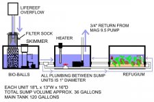
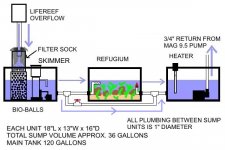
Due to the size of my stand and its main door, off-the-shelf containers with the volume I want simply will not fit. I therefore came up with a plan for a 3-unit set of custom-built acrylic containers plumbed together. I've already received a good quote on them from jensalt.com. (UPDATE: Jensalt was a HUGE mistake! Click here for details.) The total volume will be about 36 gallons. This is for a 120-gallon FOWLR tank. I have a Mag 9.5 for a return, and a LifeReef overflow box.

As you can see in the attached graphic, one sump unit contains a filter sock above it for easy mechanical filtration, housed in a Rubbermaid canister with large holes on its bottom and sides. It outflows onto a drip plate atop an eggcrate container of Bio-balls which rises partly above the waterline, providing great air/water exchange. I'm using this arrangement in my 29-gallon's DIY sump, and it works very well. On it, I have a LifeReef box and a Mag 7 for a return. (Yes, it DOES turn the water over!) Also inside the first box will be my Turboflotor 1000 skimmer, fed with an in-sump 600GPH pump.

The outflow from the first box is teed, with the main flow going to the 2nd box, containing heater, any chemicals, etc and the return pump. The secondary flow from the tee goes through a ball valve to the 3rd box, which will be a refugium with live sand and live rock. I've read a lot about how flow rates through the fuge should be lower, thus the tee and valve. The outflow from the refugium goes to the 2nd box with the return pump.

In effect, this configuration makes the 3 boxes one big sump. My only concern is that the pump would drain the 2nd (return) box and the inflow to it couldn't keep up. I think I've addressed this in the design though, since the Mag has 3/4" fittings, and I'll use 1" plumbing throughout the sump. 1" pipe has 77% more area than 3/4", so it shouldn't be a problem, and the LifeReef box can handle a huge volume of water.

I'd definitely like some other opinions on this before I build it though. All comments, criticisms, and suggestions from you experts are most welcome!

Also, am I over-engineering this? Are the concerns about flow rate through a refugium simply based on not blowing away critters? Since I intend for it to be critterless, with macroalgae only, could I eliminate the valve and use the 2nd (middle) unit as the fuge, and the 3rd one for the return? A spraybar in the fuge would spread out the stream and keep it above the sand bed, but the fuge would indeed be passing 100% of the sump's total flow through it. Would this be acceptable? If so, it would simplify and lessen the cost of the plumbing.

Thanks in advance for your input.
 

Attachments

  • sump.jpg
    sump.jpg
    47.2 KB · Views: 3,037

gbundersea

Active Reefer
Rating - 0%
0   0   0
Not possible due to location, workspace, time, and other limitations. It would be a LOT easier for me to do the 3-unit setup than modify the stand, so I'm eager to hear thoughts on it as shown. Thanks!
 

mountainbiker619

Advanced Reefer
Rating - 0%
0   0   0
looks like it would work...I would install a gate valve on the return side of the mag in order to keep all three sumps at proper water level.
 

jamesw

Advanced Reefer
Rating - 0%
0   0   0
A one inch pipe can accomodate a lot of flow, provided there is a lot of head to drive that flow.

In fact, as your diagram is drawn, there would be NO flow between the three aquariums as the water levels are all the same...:)

To get the needed head, the water level in the sump on the left is going to have to be higher...a lot higher in fact. So I would make the left sump as high as you can get away with.

Then you can start with your return pump throttled back a bit and letter' rip. If the water doesn't build up too much on the left sump, then open up the pump a bit. Repeat.

Hope that helps,
James
 
A

Anonymous

Guest
Rating - 0%
0   0   0
The skimmer will dictate how high the water can be in the first tank. Run it too high and the skimmer will flood and not work properly.

Since the return pump is in the center tank, it should suck water from the tank on the left.

I'm not sure what would happen to the tank on the left, prolly not much of anything. If you pumped water into the tank on the right, from the tank on the left, and elevated it (the tank on the right) above the water level of the middle tank, the fuge could then drain into the center tank. A small maxijet in the tank on the left could prolly do that for you.

HTH

Louey
 
A

Anonymous

Guest
Rating - 0%
0   0   0
mountainbiker, All you did was raise the plumbing. I don't think that changes anything really.

Tank one (left) gets water from the tanks drain. Tank two (middle) returns water to the tank via the pump. This will continue as long as the pump continues to operate. Tank 3 (right) just sits there. Maybe some water passes through it. Maybe not. But not much the way it is currently designed. There is nothing causing the water in tank 3 two move anywhere.

And the skimmer will not work properly with the output submerged!

Am I missing something here?

Louey
 

mountainbiker619

Advanced Reefer
Rating - 0%
0   0   0
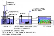
the plumbing between sump 1 and 2 will keep both sumps at a constant level, set to the heigth needed by the skimmer. Gravity will flow water from sump 3 back to sump 2 to be returned to the tank. I just think you will need some type of pump to get the water from sump 1 to sump 3..or
this below
 

Attachments

  • sump.jpg
    sump.jpg
    32.5 KB · Views: 2,950
A

Anonymous

Guest
Rating - 0%
0   0   0
What about splitting the line from the overflow to the left sump with the skimmer, and the right sump with the 'fuge and them feeding into the middle sump with the return. That way you can control the amount of water flowing through the fuge.

Oh, and I vote you nix the bio balls
 

gbundersea

Active Reefer
Rating - 0%
0   0   0
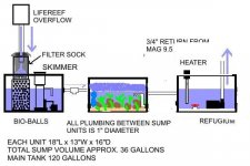
Thanks for all the discussion! I have some followups on several of the points raised. For the purposes of this post, I'll call the sumps 1, 2, and 3 as they appear left to right in my original drawing. 1=mechanical filtration/skimmer, 2=return pump, 3=refugium. (Note that the attached updated drawing is different!)

James said that having sumps 1 and 2 level results in no head pressure, thus no flow. Here's my thinking, and everyone correct (or agree with) me as you see fit. Suppose you have a single container full of water. You put a pump in it, and route the output hose back into the same container. Closed loop, no problem, right? Now, partition off the container slightly, with the output hose on the side opposite the pump. Still no problem. Keep closing the partition, but not all the way. In my view, it's STILL one big happy container, but with a partial obstruction. I'd think that as long as the gap in the partition was equal or bigger than the output diameter of the pump, it would still flow without overflowing the output "side" of the container (the one away from the pump.)

Keeping that thought, look at my sumps 1 and 2 (and 3 for that matter) as just parts of the same container, since the pipe connecting them is 77% larger than the pump output. The pump cannot physically move more water out than will come flowing back in. Granted, my "loop" is a little longer than the hypothetical one, but it runs up to the aquarium and back down through an overflow box whose capacity is huge. Whatever goes up, comes right back down. In my view, all 3 boxes should stay level. What does everyone think?

Side note: I have a Turboflotor T1000 skimmer, and am planning to feed it with a Rio 600. What's the optimum water depth? I haven't been able to find a clearcut answer. BTW, the water level shown isn't meant to be accurate.

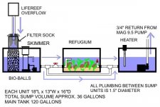
Louey was right - my original plumbing diagram was flawed. The fuge (sump 3) would have had little if any flow. I like the idea of as few pumps as possible, so rearranged it pretty much the same way as mountainbiker did. (See attached drawing.) The only issue this raises is whether this will be too much flow for the fuge. A spraybar can keep it up off the sand, but are there any problems with passing 100% of the flow through the fuge? Remember, I'm NOT planning on raising critters there.

Righty, your idea of splitting the input flow is valid, but I like having a sock for mechanical filtration, and splitting it after that point would be hard. I think my rearrangement will work fine, as long as the flow's not too much for the fuge. As for removing the balls, this will be a FOWLR tank, probably with a heavy bioload. I will keep that in mind though, as I'm planning on having a LOT of LR/LS in it. If things go well, maybe I'll try phasing the balls out after awhile and see what happens...

Again, thanks for all the input. My BIG concern is whether you think all 3 tanks will stay level, and act as effectively one big sump, with no inter-compartment flow problems. I look forward to your updated comments on the reconfigured design, and answers to the questions in this post.
 

Attachments

  • sumpa.jpg
    sumpa.jpg
    44.2 KB · Views: 2,925
A

Anonymous

Guest
Rating - 0%
0   0   0
Your revised scheme will work, but your concerns of two much flow through the fuge in legitimate one! Could you partition the fuge into 2 sections, one will high flow, the other with low flow? Use a couple of ball valve to control the flow through each section.

Louey
 

gbundersea

Active Reefer
Rating - 0%
0   0   0
Beerbaron, thanks for the link. Your design looks good, though I'm so space-limited that elevating one of the sumps may be impossible. Have you built this? If so, how's it working? Also, I think you used 1.5" diameter pipe, right? Any flow problems?

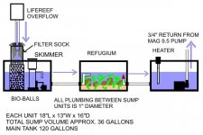
Louey, I'm thinking of a way to regulate flow through the fuge. Maybe a tee to enable a bypass loop around the fuge, with a ball valve on the bypass. That way, partially closing the valve will force flow through the fuge. See the attached updated drawing.

BTW, I like the idea of oversizing the plumbing to allow for future increases in pump size. I'll probably go with 1.5".
 

Attachments

  • sumpb.jpg
    sumpb.jpg
    47.6 KB · Views: 2,885

gbundersea

Active Reefer
Rating - 0%
0   0   0
Actually, this is better...

The valve is on the fuge, which comes straight off the tee thus would have the higher flow. Regulating it down would just force more to go through the bypass loop.

Whattya think?
 

Attachments

  • sumpb.jpg
    sumpb.jpg
    47.7 KB · Views: 2,879
A

Anonymous

Guest
Rating - 0%
0   0   0
You might need a check valve between the fuge and the bypass loop to the return. Otherwise you might get the bypass loop filling up the fuge.
 

wickerj

Experienced Reefer
Rating - 0%
0   0   0
Why don't you t off your drain line to feed your refugium, raise the bulkhead location and let it gravity feed back into the middle sump.

Jeff
 

mountainbiker619

Advanced Reefer
Rating - 0%
0   0   0
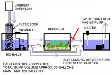
Along with the change noted below in red to let gravity flow the water into sump 3..also this is a easy way to regulate the water depth in sump 2.....Also, the line going from sump 1 to sump 3, I would make that at the same heigth (parallel) as the line going from sump 1 to sump 2. Reason why, It will take quite a bit of pressure to force the water up the 90 degree elbow joint before it going into sump 3. Running it low as in the drawing is to risky that it way overflow sump 1.
 

Attachments

  • sump.jpg
    sump.jpg
    34.7 KB · Views: 2,860

teevee

Advanced Reefer
Rating - 0%
0   0   0
if you've got room for three tanks, why not get one custom tank, split it off with baffles, get rid of the pipes and chance for spills and drilling costs, and increase water flow. your design seems overly complex.
 

Sponsor Reefs

We're a FREE website, and we exist because of hobbyists like YOU who help us run this community.

Click here to sponsor $10:


Top