
- Location
- Bay ridge, Brooklyn
[FONT=Verdana, sans-serif]LED light built[/FONT]
[FONT=Verdana, sans-serif]Few forwarding words . Please forgive my broken English, it's my second language so there might be grammar and logic mistakes in this write-up. Feel free to comment if I wrote something that doesn't make sense") [/FONT]
[/FONT]
[FONT=Verdana, sans-serif]Please also note that I am not a PRO by any means so don't use this thread as a step-to-step instruction. And be advised that playing with electricity is dangerous and you can get yourself killed if you don't know what you're doing. I take no responsibility for any fails as this thread is not a manual. Also, any suggestions and criticism are very welcome. Thank you for your understanding.[/FONT]
[FONT=Verdana, sans-serif]So I pulled the plug. After reading so much about the LEDs and seeing them in action, I decided to switch my T5s to an LED setup. It's not that T5's were a bad choice (the opposite Is true) but sometimes you want to be on top with technology and trend (right Iphone people?) so I thought ?I want it too?. No, seriously, LEDs are a great source of light and I know in couple of years they'll become a standard anyway. Few days ago I read that scientists found a way to cut costs of producing an LED emitter by 80% so I won't be surprised if the price of LED fixtures will level with current lighting options soon. [/FONT]
[FONT=Verdana, sans-serif] Unfortunately, good LED setups that use brand name emitters are still too expensive to most of us and that's why DIY is the way to go. It's one of the things I love in this hobby, you learn new things all the time. Anyway, I studied other people setups, made some sketches, asked questions 'till I was ready to build it myself. Here's how it ended up:[/FONT]
[FONT=Verdana, sans-serif]The thing is, making a DIY light is not THAT hard, but you have to prepare. First, you need to have some knowledge of electrical circuits and electronic stuff. Soldering experience is also needed, but it's not something one cannot learn. Basically, you need to know what you gonna do before you start and it's much easier if you make sketches and diagrams of your setup first. When you're ready, it's time to gather materials and tools necessary to complete it.[/FONT]
[FONT=Verdana, sans-serif]Here's a list of materials I used for my light. Some of the things like AC sockets and cable connectors are not necessary but I incorporated for the clean look and easinest of operating. .[/FONT]
[FONT=Verdana, sans-serif]-12x royal blue X-PE Cree LED's and 12x XP-G cool white Cree LEDs both mounted on a star[/FONT]
[FONT=Verdana, sans-serif]-12x 80 degree optics for the royal blue Crees (currently there's no wide angle optics for XP-G leds[/FONT]
[FONT=Verdana, sans-serif]-2x Meanwheel ELN 60-48D drivers ( I found them very easy to wire drivers, advantages are there is no need to buy a separate power supply as the driver can be plugged into ~120V source and the ?D? model is very easy to dim with external power source, also, with one meanwhell you can drive 12x 3W leds)[/FONT]
[FONT=Verdana, sans-serif]All of the above + thermal adhesive, cords and pre-cut wires came with this kit http://www.rapidled.com/servlet/the-54/24-Ultra-Premium-LED/Detail[/FONT]
[FONT=Verdana, sans-serif]-9V regulated power supply for the dimmer- it's very important to use a regulated PS cause most of the unregulated ones are giving more than they should and that can damage your LEDs easily(I used this one and it's giving constant 9.2V http://www.sparkfun.com/commerce/product_info.php?products_id=298) Please note that you only need one wallwart for dimming both drivers.[/FONT]
[FONT=Verdana, sans-serif]-electronic stuff:[/FONT]
[FONT=Verdana, sans-serif]2x120v sockets[/FONT]
[FONT=Verdana, sans-serif]4x 2.5mm DC jacks and sockets for leds[/FONT]
[FONT=Verdana, sans-serif]1x 2.1mm DC jackets and sockets for fans (it's better to use different jacks for leds and fans, that way you can't plug one into another[/FONT]
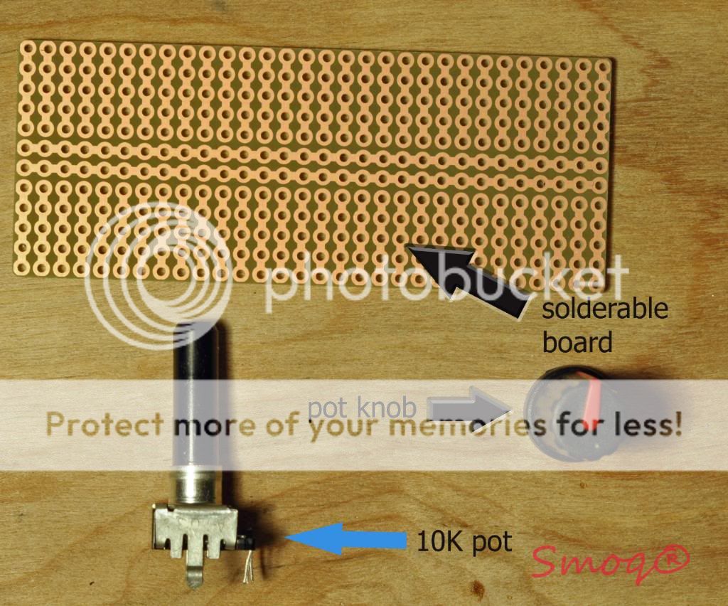
[FONT=Verdana, sans-serif]2x 10K POTS and a small board to mount them on plus pot knobs (there are other dimming options available, but I found out that using 10K pots and 9V power supply is the easiest of them and it works well)[/FONT]
[FONT=Verdana, sans-serif]female and male bullet connectors (works better than soldering the wires together IMO and it's easy to unplug it) pack of 50 each[/FONT]
[FONT=Verdana, sans-serif]18 gauge wire and 18gauge black/red cord (you can use wire anywhere between 16-22 gauge, I found 18-20 g best to work with)[/FONT]
[FONT=Verdana, sans-serif]-cooling fans- I used three of them, maybe an overkill but I rather spend more on fans that cry over burned leds One is standard pentium processor fan with heatsink that I took from computer someone threw out on the street and then there's two almost silent fans I bought here http://www.newegg.com/Product/Produ...&cm_mmc=TEMC-RMA-Approvel-_-Content-_-text-_-[/FONT]
[FONT=Verdana, sans-serif]heatshrink tubing of various sizes[/FONT]
[FONT=Verdana, sans-serif]-thermal compund to mount star to the heatsink (arctic silver thermal compound gets the best reviews)[/FONT]
[FONT=Verdana, sans-serif]-heatsink- there are options here, you can use a cut-to size heatsink with fins like the ones heatsinkusa.com are selling, or you can buy an aluminum plate which is a cheaper option but heatsink will always disperse heat better than a plate, so fans are a must with plate (and highly recommend when mounting LEDs on heatsink anyway). I bought an 0.125? aluminum plate on ebay because I spoke to some people and they all agree there's nothing wrong with mounting leds on plate instead of heatsink.[/FONT]
[FONT=Verdana, sans-serif]-plastic project box or something similar to put the drivers in (here options are unlimited, just use anything you want to hide the drivers and wires in; drivers themselves don't produce a lot of heat so cooling is not necessary) I built a project box out of plexi sheet as I couldn't find project box large enough [/FONT]
[FONT=Verdana, sans-serif]-some kind of casing/canopy for the LEDs (options are unlimited). [/FONT]
[FONT=Verdana, sans-serif]-screws to mount the stars into the heatsink/aluminum plate or a thermal adhesive. That's a serious choice here- drilling and tapping the heatsink takes a lot of time but it's very easy to replace a Led in the future. If you opt for adhesive, be warned that it's almost impossible to remove the star without damaging it once the epoxy hardens. It saves a lot of time though. I used the drilling/tapping method with 6/32 screws. [/FONT]
[FONT=Verdana, sans-serif]-plastic, heat resistant washers for the screws- that is very important, especially if you use bigger screws like I did; that way you are sure there's no electrical connection (and chance of shorts) between the screw, heatsink and wires. I used washers that come with computer motherboards, just ask your local computer service center[/FONT]
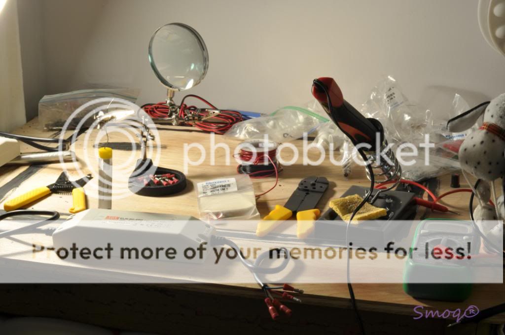
[FONT=Verdana, sans-serif]Tools:[/FONT]
[FONT=Verdana, sans-serif]There are some necessary tools you need to buy/rent/whatever in order to finish the build[/FONT]
[FONT=Verdana, sans-serif]-soldering iron- this is the single most important tool and you cannot cheap on that. While soldering wires to sockets is no hard task, soldering wires to a LED star mounted on a heatsink is a different story. The problem is aluminum pulls heat from the iron and it's hard to heat up the star enough to solder a wire into it. That's why you need a higher wattage iron and 40W is an absolute minimum IMO. To be honest with you, I've had a 40W one and it was damn hard to heat the star so I went to Home Depot and bought this thing http://www.amazon.com/dp/B0013U9R1E/?tag=reefs04-20. It works way better and heat up very quickly. It's still not the best option, but unless you want to spend $200+ on a good hot station, it's the closest alternative.[/FONT]
[FONT=Verdana, sans-serif]-solder- my opinion is, use only 60/40 rosin core solder. I tried the lead-free solder once and while it's good for your health, it sucks (doesn't stick at all)[/FONT]
[FONT=Verdana, sans-serif]-digital multimeter- also very important tool used to check connections/make sure there's no shorts and check voltage/amperage This one works well and it's inexpensive http://www.allelectronics.com/make-...-1/2-DIGIT-LCD-MULTIMETER-W/BACKLIGHT//1.html[/FONT]
[FONT=Verdana, sans-serif]-drill/driver for drilling holes for leds and to mount other parts [/FONT]
[FONT=Verdana, sans-serif]-drilling/tapping kit- people usually use 6/40 tap but I found it's easier to work with 6/32. Make sure the tap is titanium coated, otherwise it won't survive many holes[/FONT]
[FONT=Verdana, sans-serif]-screwdriver/pliers/clamps and other helpful tools[/FONT]
[FONT=Verdana, sans-serif]-space to work and desk lamp as you need to see what you're doing[/FONT]
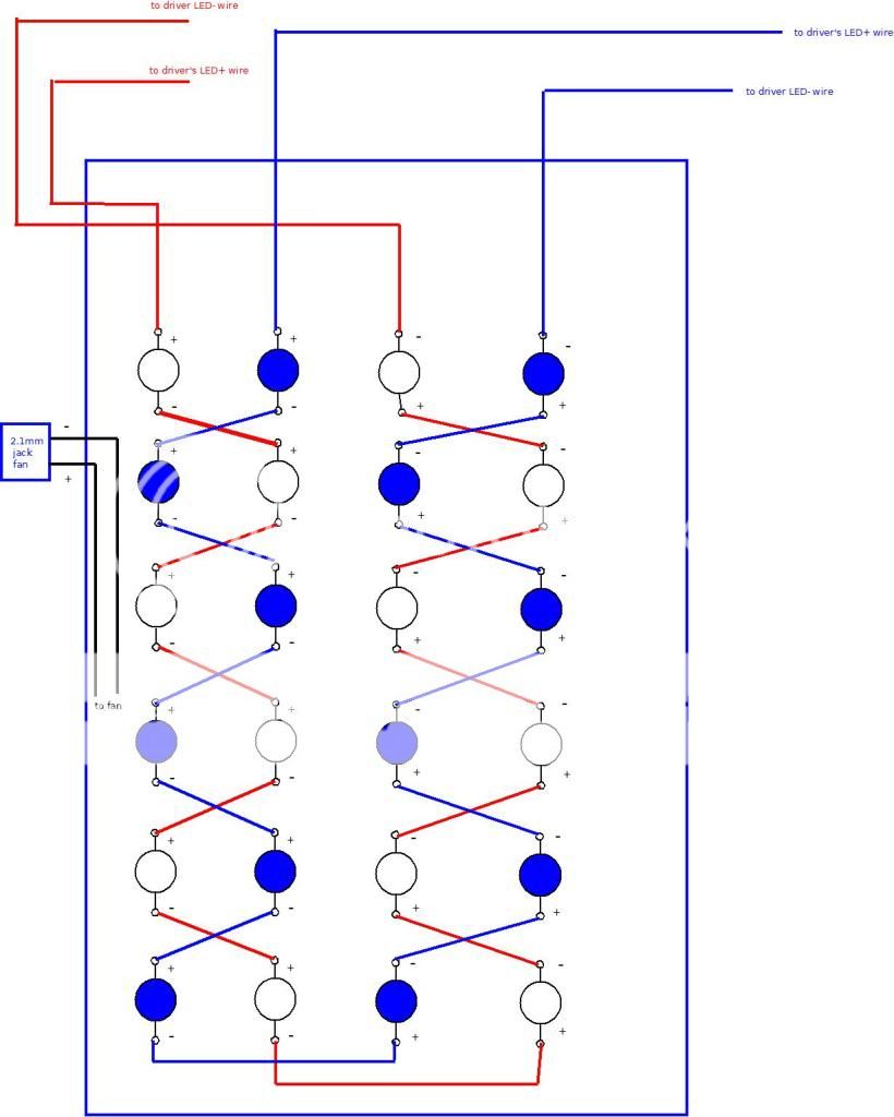
[FONT=Verdana, sans-serif]Most important stage is to have a plan and diagrams of the build. Here's mine:[/FONT]
[FONT=Verdana, sans-serif]LEDs[/FONT]
[FONT=Verdana, sans-serif]
 [/FONT]
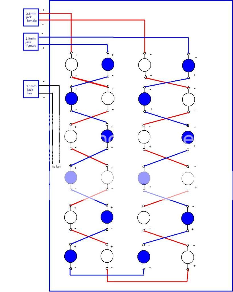
[FONT=Verdana, sans-serif]As you see there are two strings with 12LEDs each, one for white leds and one for blue . The idea is to place the leds on the board so the connecting wires are short. ?+? of first diode goes to LED+ wire on the driver (in my case there's a 2.5mm jack socket so it's easy to disconnect the light from the driver box) then the ?-? of first diode goes to ?+? of the second one and so on till you end up with ?-? of the last diode in string and that goes to driver's LED ?-?. Same is true with the blue leds. I also incorporated a 2.1mm fan jack that is powered by separate 12V wallwart[/FONT]
[FONT=Verdana, sans-serif]DRIVER BOX[/FONT]
[FONT=Verdana, sans-serif]
 [/FONT]
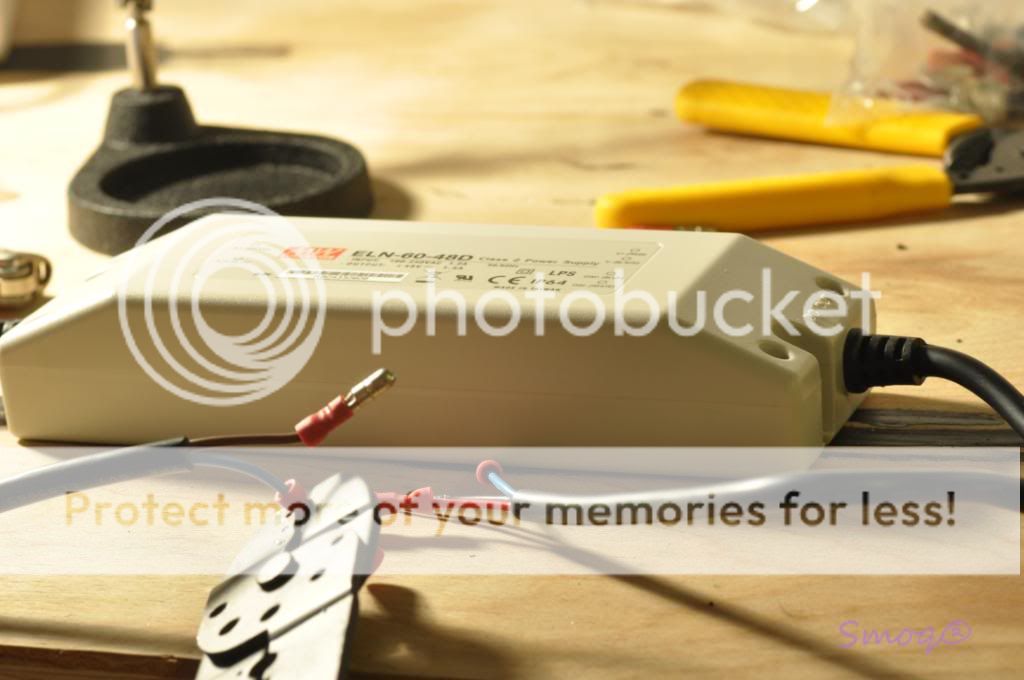
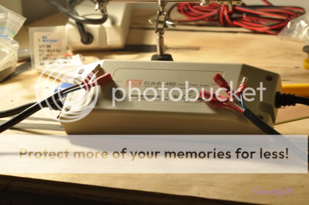
[FONT=Verdana, sans-serif]Ok, this is a little more confusing but I hope the diagram helps understand it. Let's start with drivers. They are both the same so the circuit is identical for white and blue leds. The driver has two sides, an input and output (please see fact sheet for reference http://www.meanwell.com/search/eln-60/eln-60-spec.pdf). The input side has to wires, one labeled AC/L (brown) and AC/N (blue). Those two are supposed to be connected to an AC power cable (that came with the led kit or you can use old computer power cords) and then to your wall outlet. But DON'T DO THAT NOW! This is the last thing you're gonna connect after making sure everything is connected the right way. We're clear here? OK[/FONT]
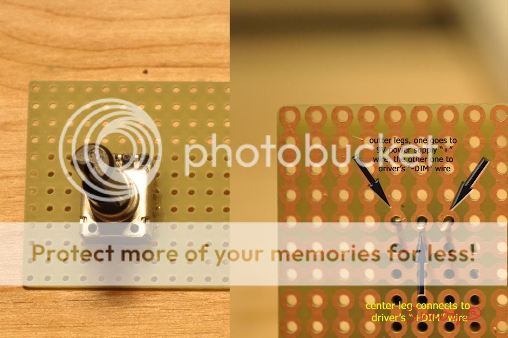
[FONT=Verdana, sans-serif]Now the output side of the driver. Here I have to say something about potentiometer. The one you need is linear 10K Ohms and it should have three legs. One outer (no matter which one just make sure you use same legs on both dimmers so you turn the pot's knob in the same direction) leg has to be connected to the ?+? of the regulated 9V power supply. The other outer leg has to be connected to the driver's ?-DIM? wire (white) for both drivers and to the ?-? of 9V power supply. It's advisable to use some kind of connector here, like wire nut, because we are speaking about five wires connected together. Finally, the center leg of the potentiometer should be connected to the ?+DIM'? wire (blue) on the meanwell. [/FONT]
[FONT=Verdana, sans-serif]The ?+V? wire (RED) on the meanwell goes into first led in a string ?+? soldering point and the ?-V? (BLACK) on the meanwell goes into ?-? soldering point on the last LED in a string. [/FONT]
[FONT=Verdana, sans-serif]Two things to remember- never connect the power to the driver before finishing all the connections as it may permanently damage LEDs and check 3 times before plugging everything in Also, if you opt for a dimmable driver you must connect a power supply to the dimmer ports, otherwise the whole thing won't power up.[/FONT]
[FONT=Verdana, sans-serif]First of all, a grid has to be drawn so you know where to place the diodes. I placed mine 2? from each other (center to center) and 2? from edge of the heatsink. I've been told that anywhere between 1.5?-3? is a good space between emitters and most people suggest 2? as a sweet point and that's how I did it.[/FONT]
[FONT=Verdana, sans-serif]When you have the grid ready, place a star so the emitter is in the center and mark two points where the screws will go. Do the same for the rest of the LEDs and you're ready to drill. Picture:[/FONT]
[FONT=Verdana, sans-serif]
 [/FONT]
[FONT=Verdana, sans-serif]Next two steps are PITA and took me some time, but once you drill/tap several holes you'll get used to it and it goes faster. First, you need to drill all the holes with the drill bit provided with the drill/tap kit. If you have a drill press, use it as it helps a lot, otherwise you have to make sure your hands are steady and that you're drilling perpendicular to the heatsink. I used a dremel and bought a dremel press and it worked great. Very good idea is to use some oil/grease while drilling metal as it will help make clean holes and saves the drillbit. WD-40 will do. [/FONT]
[FONT=Verdana, sans-serif]
 [/FONT]
[FONT=Verdana, sans-serif]When you have all the holes drilled you need to tap them for the machine screws. A tapping bit handle like the one in the picture below is helpful here. You tap by screwing the bit clockwise until you feel it's spinning freely and then pulling it out by turning clockwise. Repeat 48 times (or more depending on number of leds)[/FONT]
[FONT=Verdana, sans-serif]
 [/FONT]
[FONT=Verdana, sans-serif]Of course you can skip all that by simply gluing the star to the heatsink with thermal epoxy adhesive, your choice.[/FONT]
[FONT=Verdana, sans-serif]OK, all the holes are ready for the screws, there's nothing more than screwing LEDs to the heatsink. Make sure you put some thermal compound under each star and look for the correct poles placement (see my first diagram for reference). [/FONT]
[FONT=Verdana, sans-serif]
 [/FONT]
[FONT=Verdana, sans-serif]When all LED stars are in place, it's time for soldering. [/FONT]
[FONT=Verdana, sans-serif]I soldered all the connectors first and put a heatshrink tube on the exposed soldered connections so no 120V shock for me Skip the timer, I explain later[/FONT]
[FONT=Verdana, sans-serif]
 [/FONT]
[FONT=Verdana, sans-serif]As I mentioned before, soldering a wire to a cree star point is a little tricky because the heatsink is pulling the heat away from the star. The best is to tint all the pre-cut wires first, then heat up a soldering point on the star, put some solder on it, let it cool down and heat it up once again with the wire in other hand. When it start to melt, push the tinted wire into the melted solder on the star and remove the soldering iron's tip. It's the best, quickest method IMO as the LED can't stand high temperatures for too long. I know it's easy to say, hard to do, but with some practice it's not that hard. I forgot to take a picture of the LEDs soldered so I'll go to the next point where you can see the led panel.[/FONT]
[FONT=Verdana, sans-serif]Well, I cannot help much here as it all depends on someone's setup. You can place the led panel in a hood, build a canopy or just hang the heatsink if you don't care about the look. Here's what I did:[/FONT]
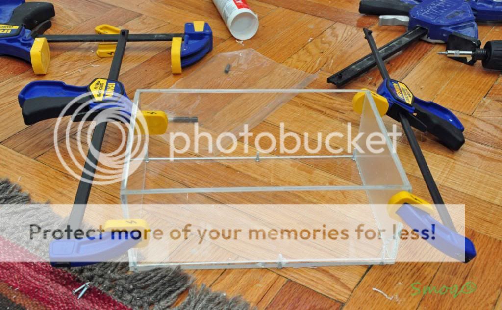
[FONT=Verdana, sans-serif]That's a plywood case I built at work (boss paid for the material, I supplied tools). It's nothing more than four plywood panels, each cut on 45 angle at ends and routered for the acrylic splash guard with a 1/4? straight bit and 1/4? from the bottom edge. One side panel was routered thru so the splashguard can be placed. [/FONT]
[FONT=Verdana, sans-serif]
 [/FONT]
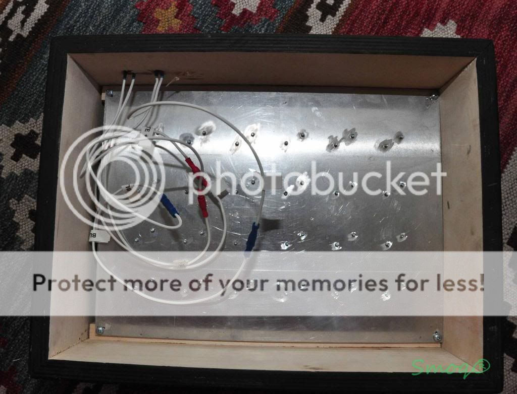
[FONT=Verdana, sans-serif]Next, I painted the thing using flat black oil paint and foam roller and mounted the heatsink plate inside the case. Here's a picture how it all looks with wires soldered between the leds. [/FONT]
[FONT=Verdana, sans-serif]
 [/FONT]
[FONT=Verdana, sans-serif]And here's the top view. Notice the bullet connectors- inexpensive, easy to unplug and less soldering. Brilliant[/FONT]
[FONT=Verdana, sans-serif]
 [/FONT]
[FONT=Verdana, sans-serif]
 [/FONT]
[FONT=Verdana, sans-serif]I screw all the panels together but it can also be siliconed. If you opt for screws, always drill the hole before screwing (I learned the hard way)[/FONT]
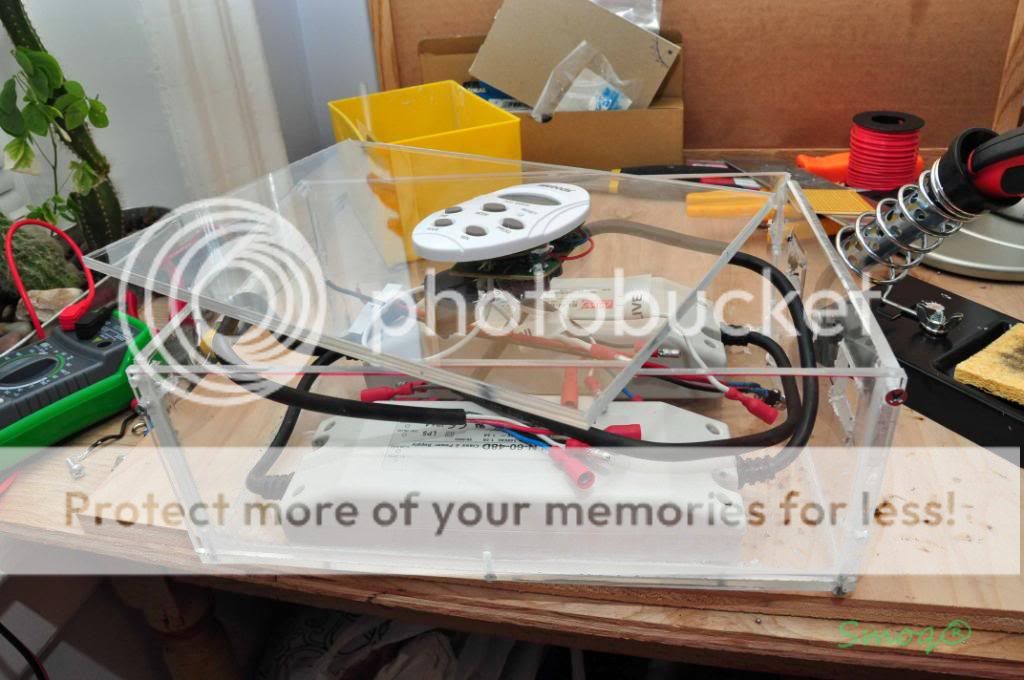
[FONT=Verdana, sans-serif]Next, I've put the drivers in, made holes for all the connectors and connected everything together. See pictures:[/FONT]
[FONT=Verdana, sans-serif]
 [/FONT]
[FONT=Verdana, sans-serif]
 [/FONT]
[FONT=Verdana, sans-serif]
 [/FONT]
[FONT=Verdana, sans-serif]I know it doesn't look great, but it was my first time working with acrylic an damn this thing is hard to cut and drill[/FONT]
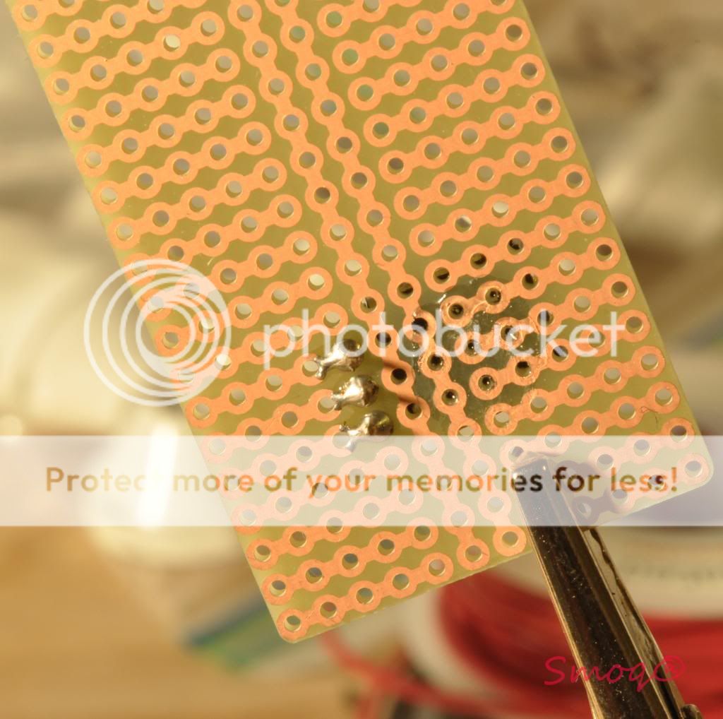
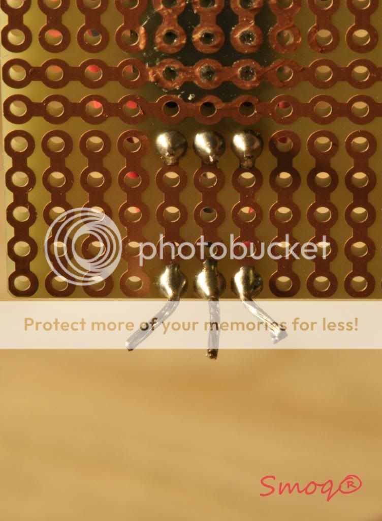
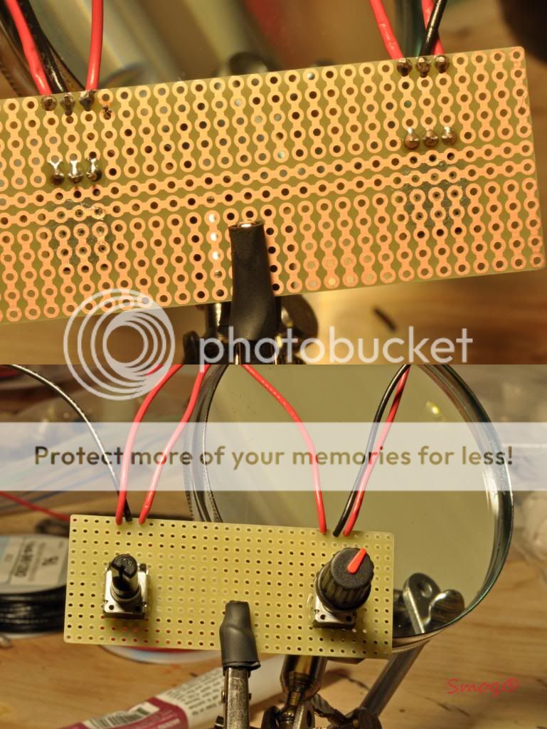
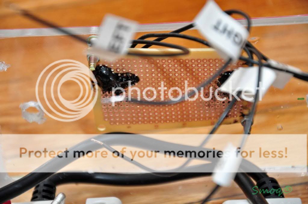
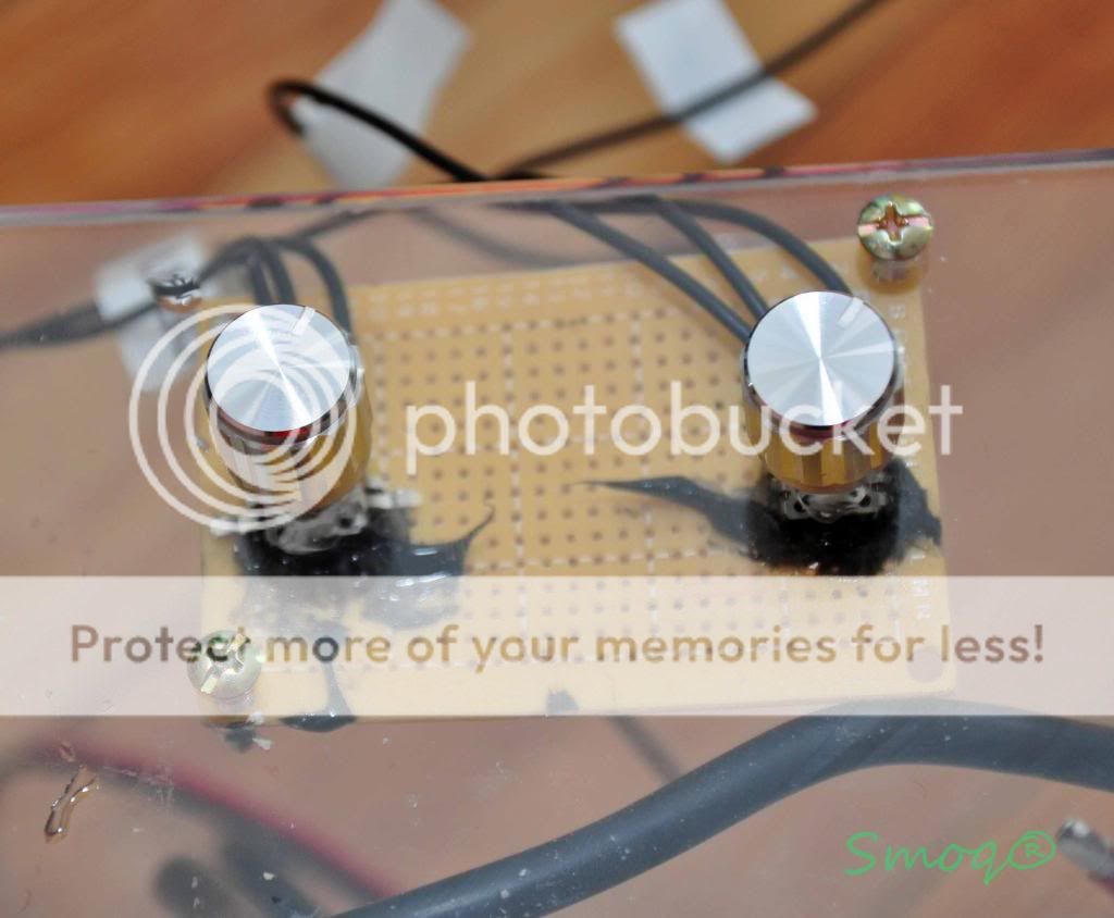
[FONT=Verdana, sans-serif]And here is the dimmer circuit setup close up. I used a bread board to mount the pots on and then soldered wires to the holes next to them. I put some silicone afterwards because the connectors are close to each other and I don't want any shorts. Glue gun is even better for that.[/FONT]
[FONT=Verdana, sans-serif]
 [/FONT]
[FONT=Verdana, sans-serif]
 [/FONT]
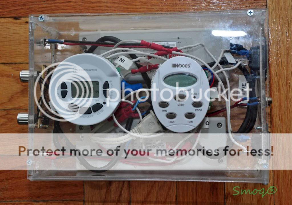
[FONT=Verdana, sans-serif]As you probably noticed, there are timers on top on the driver box. Yeah, I incorporated two ideas while doing this setup and timers were one of it. Let me explain...[/FONT]
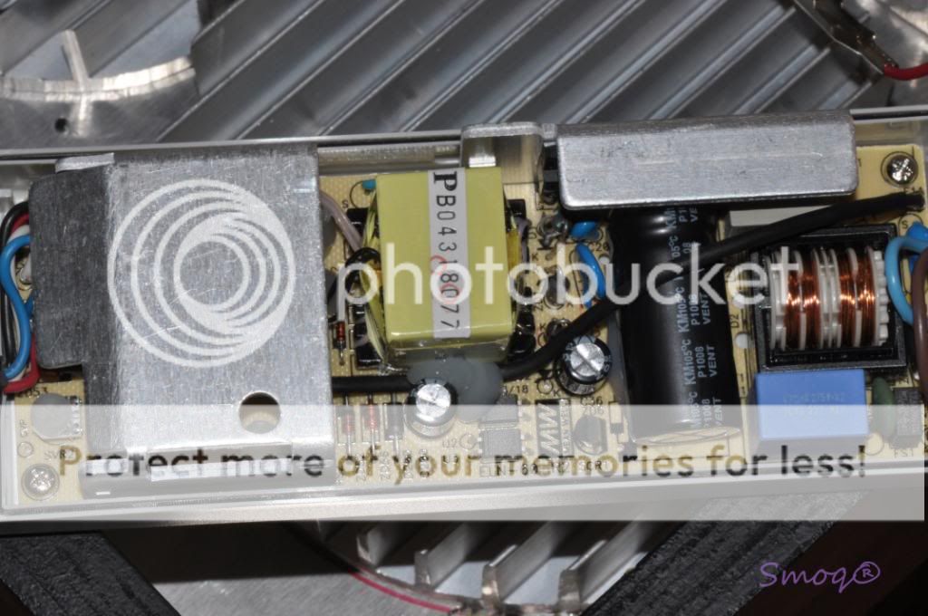
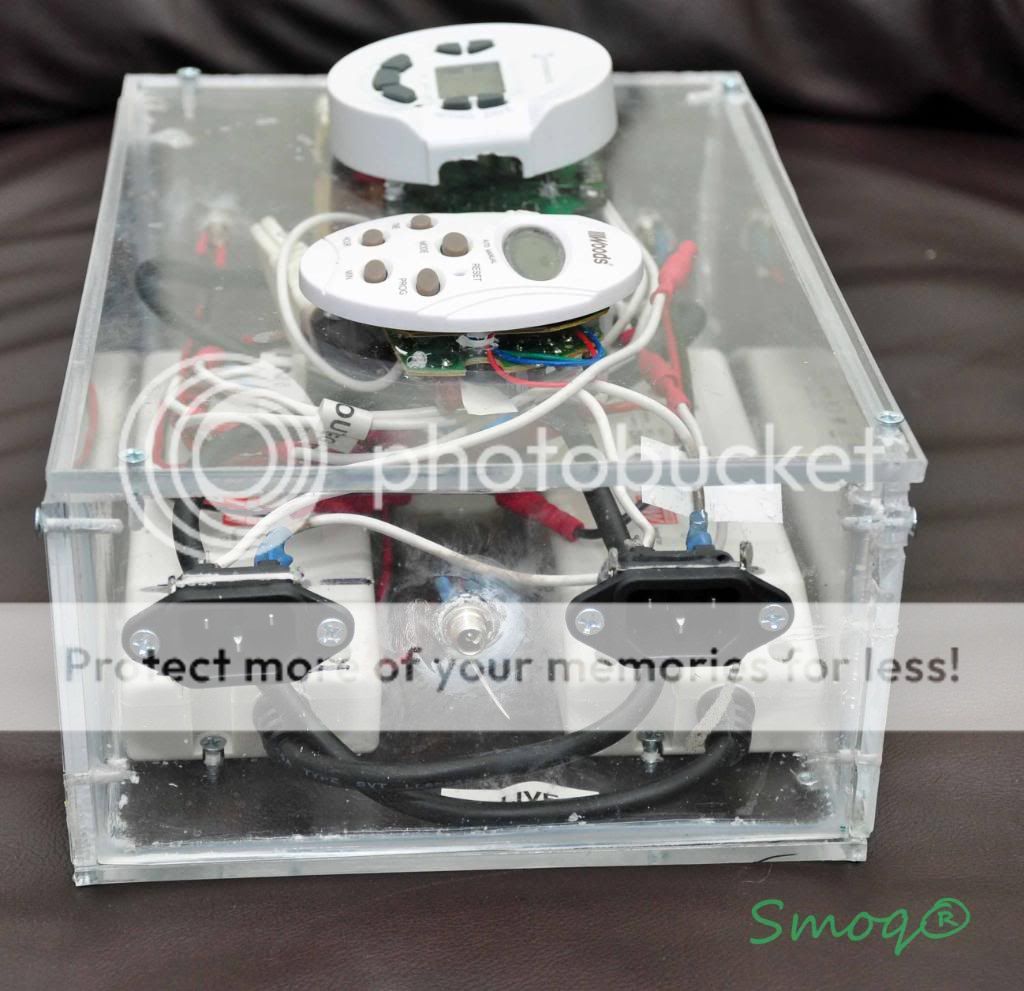
[FONT=Verdana, sans-serif]I've had two digital timers (ordinary $10 ones you can buy in Lowe's/HD) and I started playing with it I ripped them open and started to think of using them in the driver box. It's nothing complicated inside those timers so splicing them inline is not hard at all. First of all you need to get to them and de-solder the lcd screen wires from the rest of the timer. Be sure to write down and mark the correct wire placement (there were 3 wires in mine and they were all clearly labeled on the lcd and main boards. Then de-solder the input plug and solder two wires into it (locate which one is the live wire, should be written on the board). Those two wires go to your ~120V wire that goes to wall outlet (or into 120V sockets as in mine setup). Next de-solder the output outlet and again solder two wires remembering which one is live and which neutral. Those two go to the AC/L and AC/N wires on your meanwell. That way you connected an inline timer. Next, I drilled a small hole in the top panel of the driver box, pulled the three wires that will go into the timer's LCD screen, screwed the main timer board underneath the top panel and soldered the wires into the LCD screen's board. Finally, I fastened the LCD to the opposite side of the top panel and that's it. Here are some picture for better understanding this process. [/FONT]
[FONT=Verdana, sans-serif]
 [/FONT]
[FONT=Verdana, sans-serif]
 [/FONT]
[FONT=Verdana, sans-serif]
 [/FONT]
[FONT=Verdana, sans-serif]Hope that helps[/FONT]
[FONT=Verdana, sans-serif]9.Moonlight[/FONT]
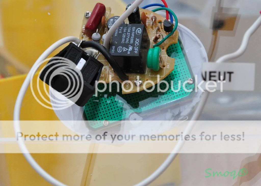
[FONT=Verdana, sans-serif]Another idea came to my mind- I didn't know how to attach the powerbrites moonlight so it won't look ghetto and I found out (after opening the thing of course) that the board that powerbrites sits on will fit between my Crees and I simply attached it where it belongs. That way I have a moonlight on separate circuit that is not taking additional space and looks good. Take a look:[/FONT]
[FONT=Verdana, sans-serif]
 [/FONT]
[FONT=Verdana, sans-serif]
[/FONT]
[FONT=Verdana, sans-serif]You can also see the wiring in the picture above.[/FONT]
[FONT=Verdana, sans-serif]
 [/FONT]
[FONT=Verdana, sans-serif]The moment of truth. Check all the connections at least three times (it's an expensive light, you don't want to cook it right?) plug all the wires except the driver input cords. Check if the 9V power supply is really giving not more than 10V and then that it stays that way under load. The last thing to do is adjust the SVR2 screw inside the meanwells. The leds should be driven at 1000mA (1A) max and it is safe to little underdrive them (I drive mine at 800mA). The SRV2 screw inside the meanwell (you need to unscrew all the screws and remove the top panel of your driver to get to it) is there to adjust the output current. Don't confuse it with the SVR1 screw as this one should be left alone. Turn it counterclockwise so the current is low, split a multimeter inline somewhere in the circuit (like between the ?V+? of the meanwell and ?+? of the first led in the string), turn the dial to A position, (in mine it is 10A) on the multimeter and turn the whole thing on (connect meanwells to the 120V outlet).Turn the pot knob all the way. The leds should power-up now. Check the current and adjust it by turning the screw until it is 700-800mA (you can go to 1A if you want, but driving them at 800mA is a lot of damn light anyway, so go figure). Do the same for the other meanwell and if everything works, you're ready to go Check if the dimmer is working and leave the whole thing for several minutes. Check if the plate/heatsink is not too hot (it should be warm to touch at max and if it's too hot to hold your hand on it, dim it down and you should think of replacing the fans with stronger ones. [/FONT]
[FONT=Verdana, sans-serif]That's it. I hope that this write-up will be helpful for all of you who are thinking of building a DIY LED light. Please comment, criticize and suggest improvements to my setup. Thanks a lot for everyone who helped me understand the whole LED setup and to everyone else who find time to read this.[/FONT]
[FONT=Verdana, sans-serif]A few pictures of the setup as I hanged it. Unfortunately I don't have a PAR meter so I can't tell you how good the LED light is, but let me just say that the corals look un-freaking-believable and the shimmer effect is great. Just by looking at the diodes you'll see that they are giving a hell amount of light, they're so damn bright.[/FONT]
[FONT=Verdana, sans-serif]
 [/FONT]
[FONT=Verdana, sans-serif]The back with all the plugs in (one for blue, one for white crees, one for dimmer and finally one for fans)[/FONT]
[FONT=Verdana, sans-serif]
 [/FONT]
[FONT=Verdana, sans-serif]
 [/FONT]
[FONT=Verdana, sans-serif]Pictures of the tank ( I forgot to say the light is hanged above an 34g Solana tank).[/FONT]
[FONT=Verdana, sans-serif]Actinics only (please note that the pictures don't do the justice, they're brighter in person)[/FONT]
[FONT=Verdana, sans-serif]
 [/FONT]
[FONT=Verdana, sans-serif]White+blue[/FONT]
[FONT=Verdana, sans-serif]
 [/FONT]
[FONT=Verdana, sans-serif]Once again, thanks and please, COMMENT[/FONT]
[FONT=Verdana, sans-serif]Few forwarding words . Please forgive my broken English, it's my second language so there might be grammar and logic mistakes in this write-up. Feel free to comment if I wrote something that doesn't make sense
[/FONT] [FONT=Verdana, sans-serif]Please also note that I am not a PRO by any means so don't use this thread as a step-to-step instruction. And be advised that playing with electricity is dangerous and you can get yourself killed if you don't know what you're doing. I take no responsibility for any fails as this thread is not a manual. Also, any suggestions and criticism are very welcome. Thank you for your understanding.[/FONT]
[FONT=Verdana, sans-serif]So I pulled the plug. After reading so much about the LEDs and seeing them in action, I decided to switch my T5s to an LED setup. It's not that T5's were a bad choice (the opposite Is true) but sometimes you want to be on top with technology and trend (right Iphone people
?) so I thought ?I want it too?. No, seriously, LEDs are a great source of light and I know in couple of years they'll become a standard anyway. Few days ago I read that scientists found a way to cut costs of producing an LED emitter by 80% so I won't be surprised if the price of LED fixtures will level with current lighting options soon. [/FONT] [FONT=Verdana, sans-serif] Unfortunately, good LED setups that use brand name emitters are still too expensive to most of us and that's why DIY is the way to go. It's one of the things I love in this hobby, you learn new things all the time. Anyway, I studied other people setups, made some sketches, asked questions 'till I was ready to build it myself. Here's how it ended up:[/FONT]
- [FONT=Verdana, sans-serif]Preparation[/FONT]
[FONT=Verdana, sans-serif]The thing is, making a DIY light is not THAT hard, but you have to prepare. First, you need to have some knowledge of electrical circuits and electronic stuff. Soldering experience is also needed, but it's not something one cannot learn. Basically, you need to know what you gonna do before you start and it's much easier if you make sketches and diagrams of your setup first. When you're ready, it's time to gather materials and tools necessary to complete it.[/FONT]
- [FONT=Verdana, sans-serif]Materials and tools:[/FONT]
[FONT=Verdana, sans-serif]Here's a list of materials I used for my light. Some of the things like AC sockets and cable connectors are not necessary but I incorporated for the clean look and easinest of operating. .[/FONT]
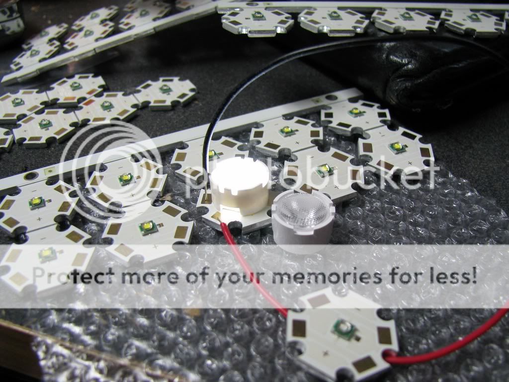
[FONT=Verdana, sans-serif]-12x royal blue X-PE Cree LED's and 12x XP-G cool white Cree LEDs both mounted on a star[/FONT]
[FONT=Verdana, sans-serif]-12x 80 degree optics for the royal blue Crees (currently there's no wide angle optics for XP-G leds[/FONT]
[FONT=Verdana, sans-serif]-2x Meanwheel ELN 60-48D drivers ( I found them very easy to wire drivers, advantages are there is no need to buy a separate power supply as the driver can be plugged into ~120V source and the ?D? model is very easy to dim with external power source, also, with one meanwhell you can drive 12x 3W leds)[/FONT]
[FONT=Verdana, sans-serif]All of the above + thermal adhesive, cords and pre-cut wires came with this kit http://www.rapidled.com/servlet/the-54/24-Ultra-Premium-LED/Detail[/FONT]
[FONT=Verdana, sans-serif]-9V regulated power supply for the dimmer- it's very important to use a regulated PS cause most of the unregulated ones are giving more than they should and that can damage your LEDs easily(I used this one and it's giving constant 9.2V http://www.sparkfun.com/commerce/product_info.php?products_id=298) Please note that you only need one wallwart for dimming both drivers.[/FONT]
[FONT=Verdana, sans-serif]-electronic stuff:[/FONT]
[FONT=Verdana, sans-serif]2x120v sockets[/FONT]
[FONT=Verdana, sans-serif]4x 2.5mm DC jacks and sockets for leds[/FONT]
[FONT=Verdana, sans-serif]1x 2.1mm DC jackets and sockets for fans (it's better to use different jacks for leds and fans, that way you can't plug one into another[/FONT]
[FONT=Verdana, sans-serif]2x 10K POTS and a small board to mount them on plus pot knobs (there are other dimming options available, but I found out that using 10K pots and 9V power supply is the easiest of them and it works well)[/FONT]
[FONT=Verdana, sans-serif]female and male bullet connectors (works better than soldering the wires together IMO and it's easy to unplug it) pack of 50 each[/FONT]
[FONT=Verdana, sans-serif]18 gauge wire and 18gauge black/red cord (you can use wire anywhere between 16-22 gauge, I found 18-20 g best to work with)[/FONT]
[FONT=Verdana, sans-serif]-cooling fans- I used three of them, maybe an overkill but I rather spend more on fans that cry over burned leds
One is standard pentium processor fan with heatsink that I took from computer someone threw out on the street and then there's two almost silent fans I bought here http://www.newegg.com/Product/Produ...&cm_mmc=TEMC-RMA-Approvel-_-Content-_-text-_-[/FONT][FONT=Verdana, sans-serif]heatshrink tubing of various sizes[/FONT]
[FONT=Verdana, sans-serif]-thermal compund to mount star to the heatsink (arctic silver thermal compound gets the best reviews)[/FONT]
[FONT=Verdana, sans-serif]-heatsink- there are options here, you can use a cut-to size heatsink with fins like the ones heatsinkusa.com are selling, or you can buy an aluminum plate which is a cheaper option but heatsink will always disperse heat better than a plate, so fans are a must with plate (and highly recommend when mounting LEDs on heatsink anyway
). I bought an 0.125? aluminum plate on ebay because I spoke to some people and they all agree there's nothing wrong with mounting leds on plate instead of heatsink.[/FONT][FONT=Verdana, sans-serif]-plastic project box or something similar to put the drivers in (here options are unlimited, just use anything you want to hide the drivers and wires in; drivers themselves don't produce a lot of heat so cooling is not necessary) I built a project box out of plexi sheet as I couldn't find project box large enough [/FONT]
[FONT=Verdana, sans-serif]-some kind of casing/canopy for the LEDs (options are unlimited). [/FONT]
[FONT=Verdana, sans-serif]-screws to mount the stars into the heatsink/aluminum plate or a thermal adhesive. That's a serious choice here- drilling and tapping the heatsink takes a lot of time but it's very easy to replace a Led in the future. If you opt for adhesive, be warned that it's almost impossible to remove the star without damaging it once the epoxy hardens. It saves a lot of time though. I used the drilling/tapping method with 6/32 screws. [/FONT]
[FONT=Verdana, sans-serif]-plastic, heat resistant washers for the screws- that is very important, especially if you use bigger screws like I did; that way you are sure there's no electrical connection (and chance of shorts) between the screw, heatsink and wires. I used washers that come with computer motherboards, just ask your local computer service center[/FONT]
[FONT=Verdana, sans-serif]Tools:[/FONT]
[FONT=Verdana, sans-serif]There are some necessary tools you need to buy/rent/whatever in order to finish the build[/FONT]
[FONT=Verdana, sans-serif]-soldering iron- this is the single most important tool and you cannot cheap on that. While soldering wires to sockets is no hard task, soldering wires to a LED star mounted on a heatsink is a different story. The problem is aluminum pulls heat from the iron and it's hard to heat up the star enough to solder a wire into it. That's why you need a higher wattage iron and 40W is an absolute minimum IMO. To be honest with you, I've had a 40W one and it was damn hard to heat the star so I went to Home Depot and bought this thing http://www.amazon.com/dp/B0013U9R1E/?tag=reefs04-20. It works way better and heat up very quickly. It's still not the best option, but unless you want to spend $200+ on a good hot station, it's the closest alternative.[/FONT]
[FONT=Verdana, sans-serif]-solder- my opinion is, use only 60/40 rosin core solder. I tried the lead-free solder once and while it's good for your health, it sucks (doesn't stick at all)[/FONT]
[FONT=Verdana, sans-serif]-digital multimeter- also very important tool used to check connections/make sure there's no shorts and check voltage/amperage This one works well and it's inexpensive http://www.allelectronics.com/make-...-1/2-DIGIT-LCD-MULTIMETER-W/BACKLIGHT//1.html[/FONT]
[FONT=Verdana, sans-serif]-drill/driver for drilling holes for leds and to mount other parts [/FONT]
[FONT=Verdana, sans-serif]-drilling/tapping kit- people usually use 6/40 tap but I found it's easier to work with 6/32. Make sure the tap is titanium coated, otherwise it won't survive many holes[/FONT]
[FONT=Verdana, sans-serif]-screwdriver/pliers/clamps and other helpful tools[/FONT]
[FONT=Verdana, sans-serif]-space to work and desk lamp as you need to see what you're doing
[/FONT]- [FONT=Verdana, sans-serif]Planning[/FONT]
[FONT=Verdana, sans-serif]Most important stage is to have a plan and diagrams of the build. Here's mine:[/FONT]
[FONT=Verdana, sans-serif]LEDs[/FONT]
[FONT=Verdana, sans-serif]
[FONT=Verdana, sans-serif]As you see there are two strings with 12LEDs each, one for white leds and one for blue . The idea is to place the leds on the board so the connecting wires are short. ?+? of first diode goes to LED+ wire on the driver (in my case there's a 2.5mm jack socket so it's easy to disconnect the light from the driver box) then the ?-? of first diode goes to ?+? of the second one and so on till you end up with ?-? of the last diode in string and that goes to driver's LED ?-?. Same is true with the blue leds. I also incorporated a 2.1mm fan jack that is powered by separate 12V wallwart[/FONT]
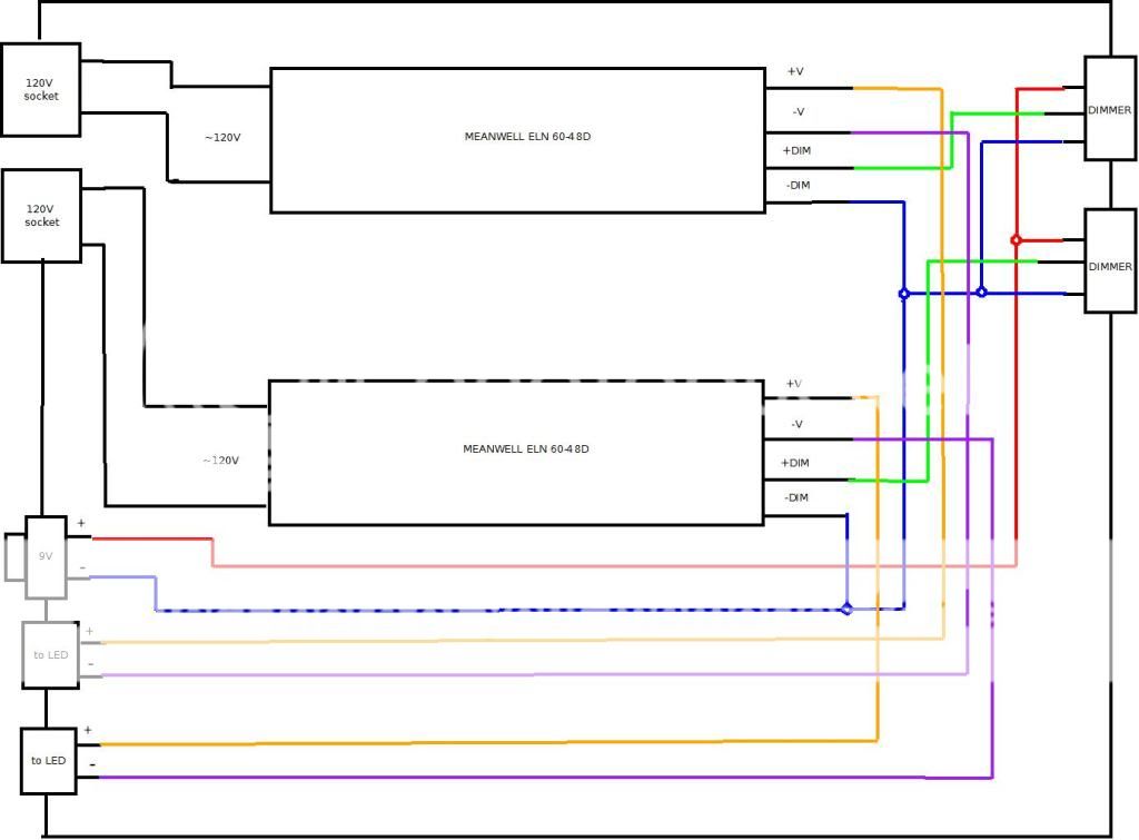
[FONT=Verdana, sans-serif]DRIVER BOX[/FONT]
[FONT=Verdana, sans-serif]
[FONT=Verdana, sans-serif]Ok, this is a little more confusing but I hope the diagram helps understand it. Let's start with drivers. They are both the same so the circuit is identical for white and blue leds. The driver has two sides, an input and output (please see fact sheet for reference http://www.meanwell.com/search/eln-60/eln-60-spec.pdf). The input side has to wires, one labeled AC/L (brown) and AC/N (blue). Those two are supposed to be connected to an AC power cable (that came with the led kit or you can use old computer power cords) and then to your wall outlet. But DON'T DO THAT NOW! This is the last thing you're gonna connect after making sure everything is connected the right way. We're clear here? OK
[/FONT][FONT=Verdana, sans-serif]Now the output side of the driver. Here I have to say something about potentiometer. The one you need is linear 10K Ohms and it should have three legs. One outer (no matter which one just make sure you use same legs on both dimmers so you turn the pot's knob in the same direction) leg has to be connected to the ?+? of the regulated 9V power supply. The other outer leg has to be connected to the driver's ?-DIM? wire (white) for both drivers and to the ?-? of 9V power supply. It's advisable to use some kind of connector here, like wire nut, because we are speaking about five wires connected together. Finally, the center leg of the potentiometer should be connected to the ?+DIM'? wire (blue) on the meanwell. [/FONT]
[FONT=Verdana, sans-serif]The ?+V? wire (RED) on the meanwell goes into first led in a string ?+? soldering point and the ?-V? (BLACK) on the meanwell goes into ?-? soldering point on the last LED in a string. [/FONT]
[FONT=Verdana, sans-serif]Two things to remember- never connect the power to the driver before finishing all the connections as it may permanently damage LEDs and check 3 times before plugging everything in
Also, if you opt for a dimmable driver you must connect a power supply to the dimmer ports, otherwise the whole thing won't power up.[/FONT]- [FONT=Verdana, sans-serif]Drilling/tapping[/FONT]
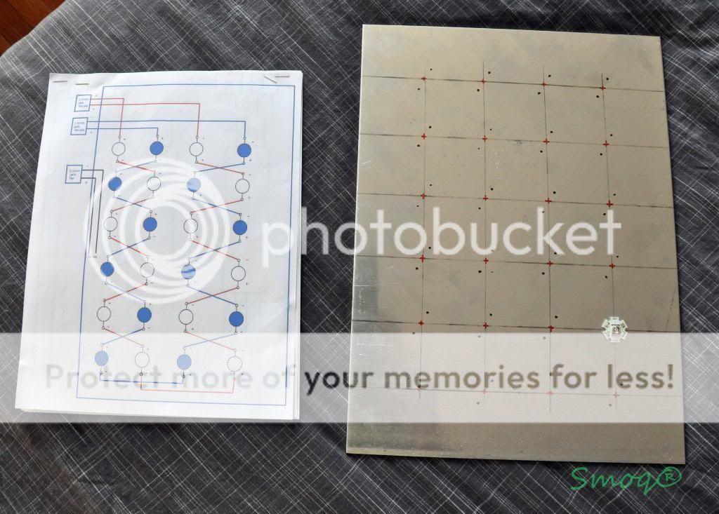
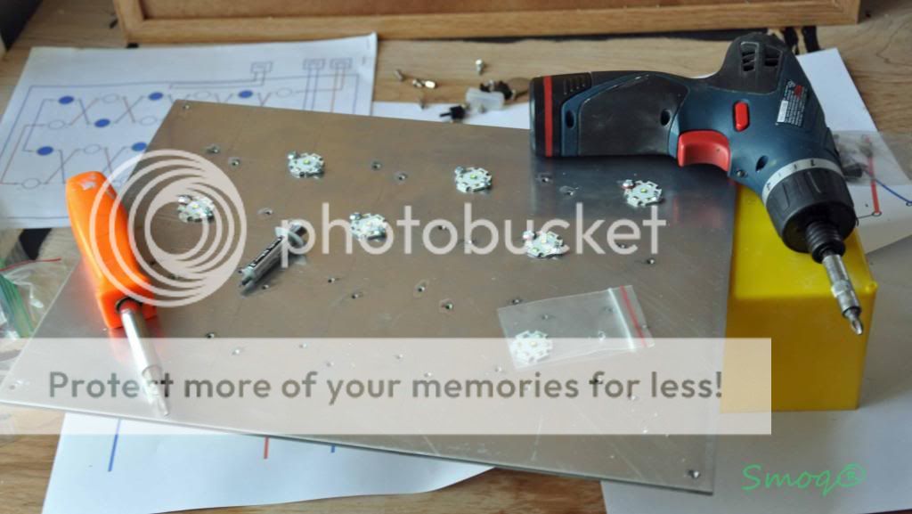
[FONT=Verdana, sans-serif]First of all, a grid has to be drawn so you know where to place the diodes. I placed mine 2? from each other (center to center) and 2? from edge of the heatsink. I've been told that anywhere between 1.5?-3? is a good space between emitters and most people suggest 2? as a sweet point and that's how I did it.[/FONT]
[FONT=Verdana, sans-serif]When you have the grid ready, place a star so the emitter is in the center and mark two points where the screws will go. Do the same for the rest of the LEDs and you're ready to drill. Picture:[/FONT]
[FONT=Verdana, sans-serif]
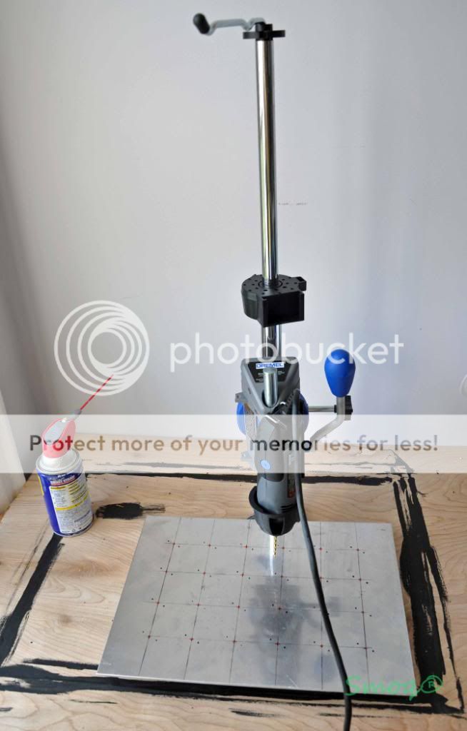
[FONT=Verdana, sans-serif]Next two steps are PITA and took me some time, but once you drill/tap several holes you'll get used to it and it goes faster. First, you need to drill all the holes with the drill bit provided with the drill/tap kit. If you have a drill press, use it as it helps a lot, otherwise you have to make sure your hands are steady and that you're drilling perpendicular to the heatsink. I used a dremel and bought a dremel press and it worked great. Very good idea is to use some oil/grease while drilling metal as it will help make clean holes and saves the drillbit. WD-40 will do. [/FONT]
[FONT=Verdana, sans-serif]
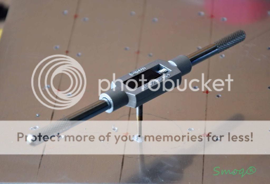
[FONT=Verdana, sans-serif]When you have all the holes drilled you need to tap them for the machine screws. A tapping bit handle like the one in the picture below is helpful here. You tap by screwing the bit clockwise until you feel it's spinning freely and then pulling it out by turning clockwise. Repeat 48 times
(or more depending on number of leds)[/FONT][FONT=Verdana, sans-serif]
[FONT=Verdana, sans-serif]Of course you can skip all that by simply gluing the star to the heatsink with thermal epoxy adhesive, your choice.[/FONT]
[FONT=Verdana, sans-serif]OK, all the holes are ready for the screws, there's nothing more than screwing LEDs to the heatsink. Make sure you put some thermal compound under each star and look for the correct poles placement (see my first diagram for reference). [/FONT]
[FONT=Verdana, sans-serif]
[FONT=Verdana, sans-serif]When all LED stars are in place, it's time for soldering. [/FONT]
- [FONT=Verdana, sans-serif]Soldering[/FONT]
[FONT=Verdana, sans-serif]There are some basics of soldering that I don't want to dig into, but if you don't have any experience, practice on some old computer boards and do first all the wires and connectors before soldering the LEDs as they are the hardest to solder. May I suggest you this guy's video, he explains it way better than I'll ever do http://www.youtube.com/watch?v=BLfXXRfRIzY[/FONT]
[FONT=Verdana, sans-serif]This site is good also. http://www.mediacollege.com/misc/solder/[/FONT]
[FONT=Verdana, sans-serif]I soldered all the connectors first and put a heatshrink tube on the exposed soldered connections so no 120V shock for me
Skip the timer, I explain later[/FONT][FONT=Verdana, sans-serif]
[FONT=Verdana, sans-serif]As I mentioned before, soldering a wire to a cree star point is a little tricky because the heatsink is pulling the heat away from the star. The best is to tint all the pre-cut wires first, then heat up a soldering point on the star, put some solder on it, let it cool down and heat it up once again with the wire in other hand. When it start to melt, push the tinted wire into the melted solder on the star and remove the soldering iron's tip. It's the best, quickest method IMO as the LED can't stand high temperatures for too long. I know it's easy to say, hard to do, but with some practice it's not that hard. I forgot to take a picture of the LEDs soldered so I'll go to the next point where you can see the led panel.[/FONT]
- [FONT=Verdana, sans-serif]Canopy/casing[/FONT]
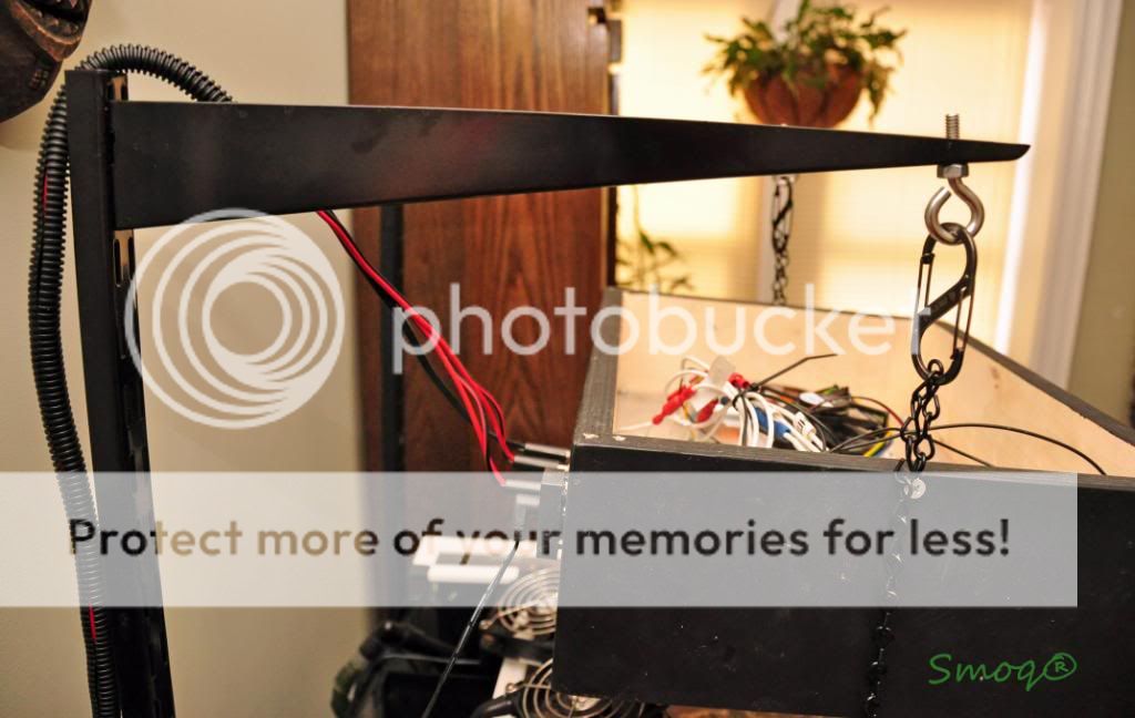
[FONT=Verdana, sans-serif]Well, I cannot help much here as it all depends on someone's setup. You can place the led panel in a hood, build a canopy or just hang the heatsink if you don't care about the look. Here's what I did:[/FONT]
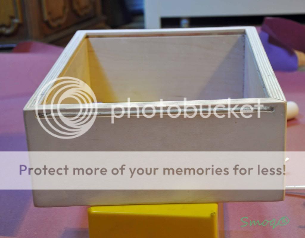
[FONT=Verdana, sans-serif]That's a plywood case I built at work (boss paid for the material, I supplied tools
). It's nothing more than four plywood panels, each cut on 45 angle at ends and routered for the acrylic splash guard with a 1/4? straight bit and 1/4? from the bottom edge. One side panel was routered thru so the splashguard can be placed. [/FONT] [FONT=Verdana, sans-serif]
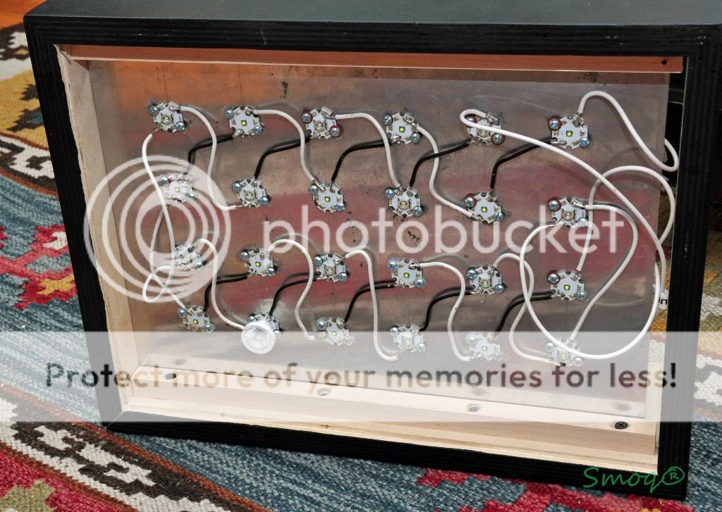
[FONT=Verdana, sans-serif]Next, I painted the thing using flat black oil paint and foam roller and mounted the heatsink plate inside the case. Here's a picture how it all looks with wires soldered between the leds. [/FONT]
[FONT=Verdana, sans-serif]
[FONT=Verdana, sans-serif]And here's the top view. Notice the bullet connectors- inexpensive, easy to unplug and less soldering. Brilliant
[/FONT][FONT=Verdana, sans-serif]
- [FONT=Verdana, sans-serif]Driver box[/FONT]
[FONT=Verdana, sans-serif]
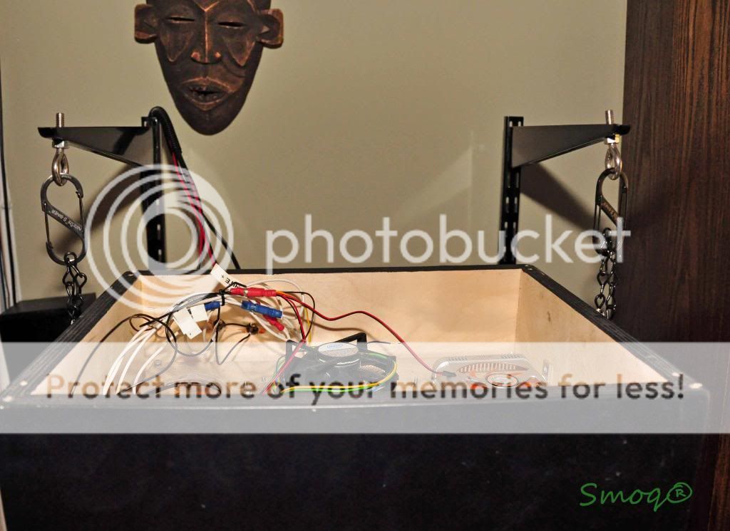
[FONT=Verdana, sans-serif]I screw all the panels together but it can also be siliconed. If you opt for screws, always drill the hole before screwing (I learned the hard way
)[/FONT][FONT=Verdana, sans-serif]Next, I've put the drivers in, made holes for all the connectors and connected everything together. See pictures:[/FONT]
[FONT=Verdana, sans-serif]
[FONT=Verdana, sans-serif]
[FONT=Verdana, sans-serif]
[FONT=Verdana, sans-serif]I know it doesn't look great, but it was my first time working with acrylic an damn this thing is hard to cut and drill
[/FONT][FONT=Verdana, sans-serif]And here is the dimmer circuit setup close up. I used a bread board to mount the pots on and then soldered wires to the holes next to them. I put some silicone afterwards because the connectors are close to each other and I don't want any shorts. Glue gun is even better for that.[/FONT]
[FONT=Verdana, sans-serif]
[FONT=Verdana, sans-serif]
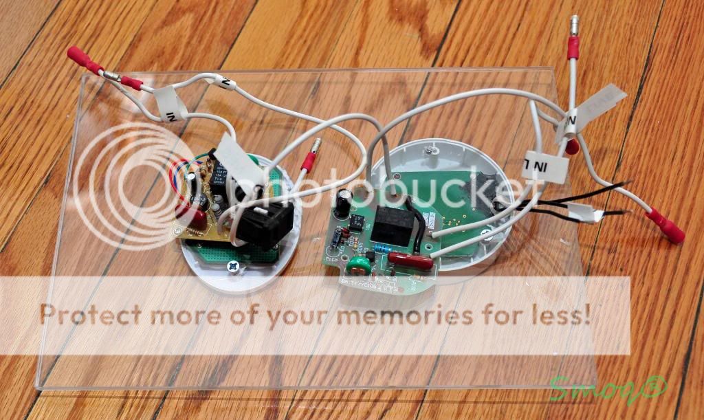
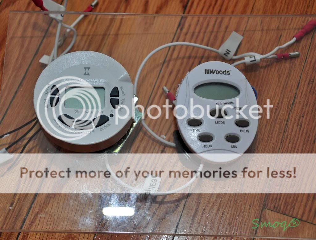
[FONT=Verdana, sans-serif]As you probably noticed, there are timers on top on the driver box. Yeah, I incorporated two ideas while doing this setup and timers were one of it. Let me explain...[/FONT]
- [FONT=Verdana, sans-serif]Timers[/FONT]
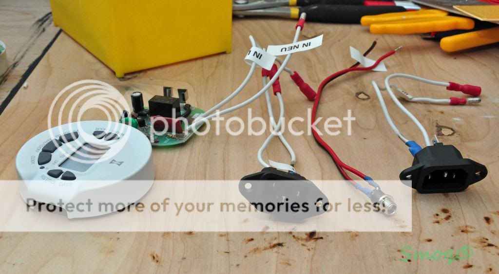
[FONT=Verdana, sans-serif]I've had two digital timers (ordinary $10 ones you can buy in Lowe's/HD) and I started playing with it
I ripped them open and started to think of using them in the driver box. It's nothing complicated inside those timers so splicing them inline is not hard at all. First of all you need to get to them and de-solder the lcd screen wires from the rest of the timer. Be sure to write down and mark the correct wire placement (there were 3 wires in mine and they were all clearly labeled on the lcd and main boards. Then de-solder the input plug and solder two wires into it (locate which one is the live wire, should be written on the board). Those two wires go to your ~120V wire that goes to wall outlet (or into 120V sockets as in mine setup). Next de-solder the output outlet and again solder two wires remembering which one is live and which neutral. Those two go to the AC/L and AC/N wires on your meanwell. That way you connected an inline timer. Next, I drilled a small hole in the top panel of the driver box, pulled the three wires that will go into the timer's LCD screen, screwed the main timer board underneath the top panel and soldered the wires into the LCD screen's board. Finally, I fastened the LCD to the opposite side of the top panel and that's it. Here are some picture for better understanding this process. [/FONT] [FONT=Verdana, sans-serif]
[FONT=Verdana, sans-serif]
[FONT=Verdana, sans-serif]
[FONT=Verdana, sans-serif]Hope that helps[/FONT]
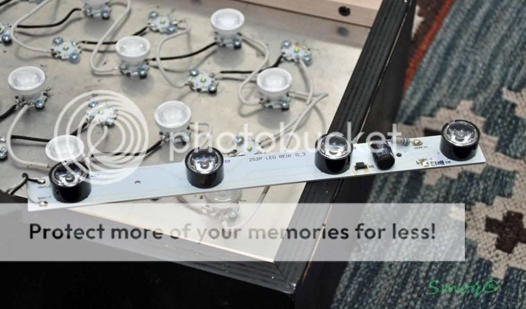
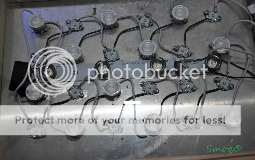
[FONT=Verdana, sans-serif]9.Moonlight[/FONT]
[FONT=Verdana, sans-serif]Another idea came to my mind- I didn't know how to attach the powerbrites moonlight so it won't look ghetto and I found out (after opening the thing of course) that the board that powerbrites sits on will fit between my Crees and I simply attached it where it belongs
. That way I have a moonlight on separate circuit that is not taking additional space and looks good. Take a look:[/FONT][FONT=Verdana, sans-serif]
[FONT=Verdana, sans-serif]
[/FONT]
[FONT=Verdana, sans-serif]You can also see the wiring in the picture above.[/FONT]
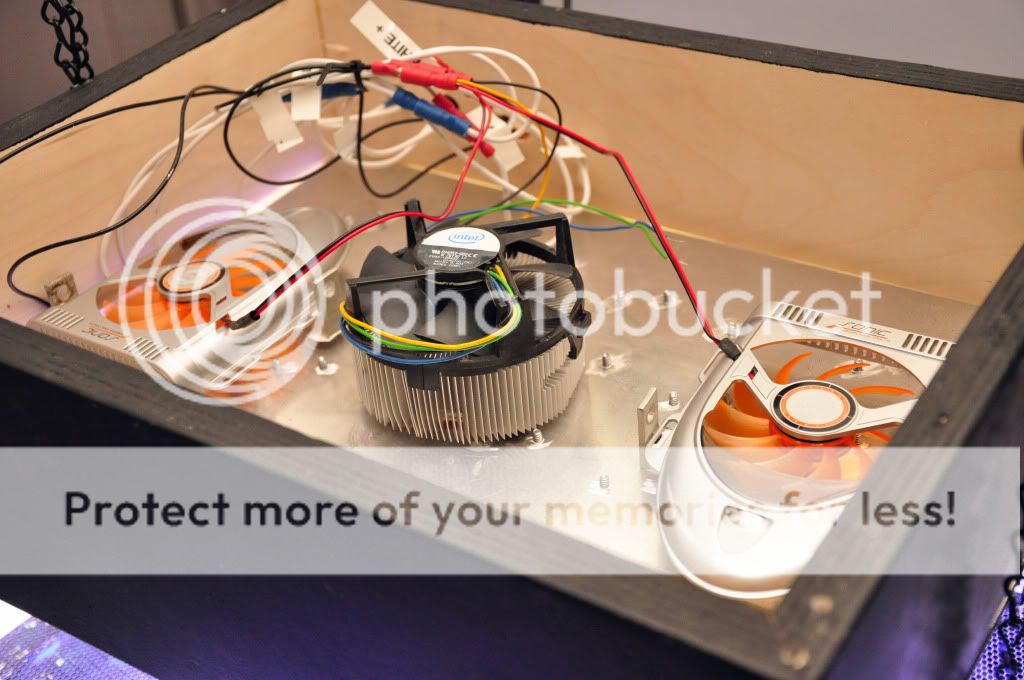
- [FONT=Verdana, sans-serif]Fans[/FONT]
[FONT=Verdana, sans-serif]
- [FONT=Verdana, sans-serif]Testing/adjusting.[/FONT]
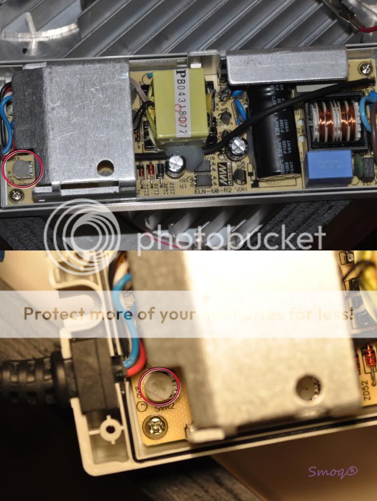
[FONT=Verdana, sans-serif]The moment of truth. Check all the connections at least three times (it's an expensive light, you don't want to cook it right?) plug all the wires except the driver input cords. Check if the 9V power supply is really giving not more than 10V and then that it stays that way under load. The last thing to do is adjust the SVR2 screw inside the meanwells. The leds should be driven at 1000mA (1A) max and it is safe to little underdrive them (I drive mine at 800mA). The SRV2 screw inside the meanwell (you need to unscrew all the screws and remove the top panel of your driver to get to it) is there to adjust the output current. Don't confuse it with the SVR1 screw as this one should be left alone. Turn it counterclockwise so the current is low, split a multimeter inline somewhere in the circuit (like between the ?V+? of the meanwell and ?+? of the first led in the string), turn the dial to A position, (in mine it is 10A) on the multimeter and turn the whole thing on (connect meanwells to the 120V outlet).Turn the pot knob all the way. The leds should power-up now. Check the current and adjust it by turning the screw until it is 700-800mA (you can go to 1A if you want, but driving them at 800mA is a lot of damn light anyway, so go figure). Do the same for the other meanwell and if everything works, you're ready to go
Check if the dimmer is working and leave the whole thing for several minutes. Check if the plate/heatsink is not too hot (it should be warm to touch at max and if it's too hot to hold your hand on it, dim it down and you should think of replacing the fans with stronger ones. [/FONT] [FONT=Verdana, sans-serif]That's it. I hope that this write-up will be helpful for all of you who are thinking of building a DIY LED light. Please comment, criticize and suggest improvements to my setup. Thanks a lot for everyone who helped me understand the whole LED setup and to everyone else who find time to read this.[/FONT]
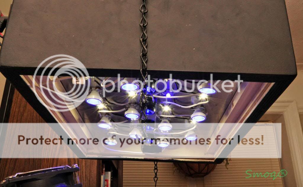
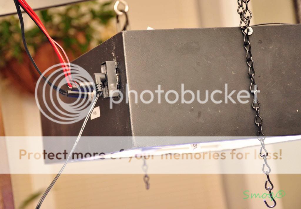
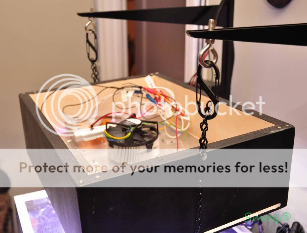
[FONT=Verdana, sans-serif]A few pictures of the setup as I hanged it. Unfortunately I don't have a PAR meter so I can't tell you how good the LED light is, but let me just say that the corals look un-freaking-believable and the shimmer effect is great. Just by looking at the diodes you'll see that they are giving a hell amount of light, they're so damn bright.[/FONT]
[FONT=Verdana, sans-serif]
[FONT=Verdana, sans-serif]The back with all the plugs in (one for blue, one for white crees, one for dimmer and finally one for fans)[/FONT]
[FONT=Verdana, sans-serif]
[FONT=Verdana, sans-serif]
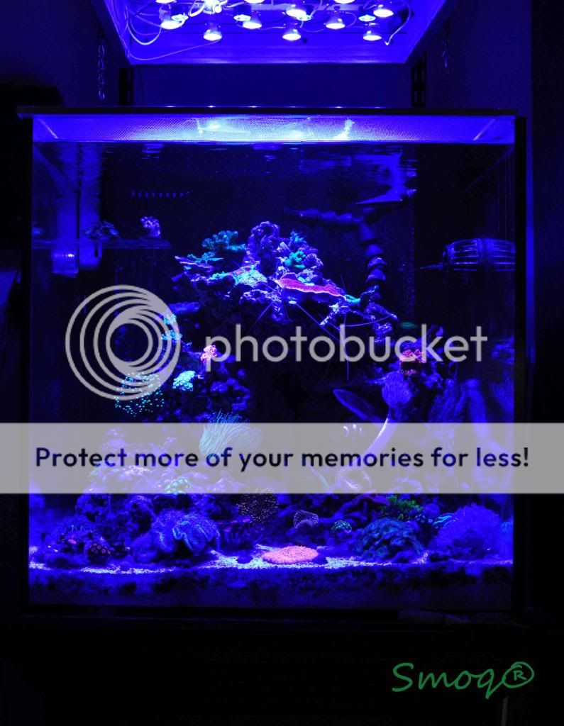
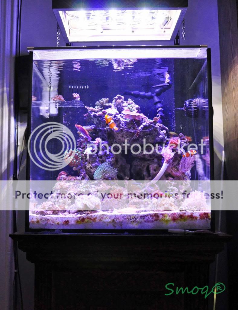
[FONT=Verdana, sans-serif]Pictures of the tank ( I forgot to say the light is hanged above an 34g Solana tank).[/FONT]
[FONT=Verdana, sans-serif]Actinics only (please note that the pictures don't do the justice, they're brighter in person)[/FONT]
[FONT=Verdana, sans-serif]
[FONT=Verdana, sans-serif]White+blue[/FONT]
[FONT=Verdana, sans-serif]
[FONT=Verdana, sans-serif]Once again, thanks and please, COMMENT
[/FONT]