LED built ver 2.0
Long story short- I upgraded to a bigger tank, made another LED pendant and decided to update my led built thread. I received many PMs regarding the write-up and here is my attempt to explain in details some aspects of building led light and I'll try to clear some things I didn't explain quite right the last time

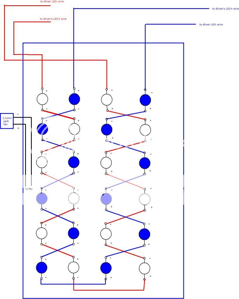
I. First of all, here is an updated LED board scheme, I hope it will clear things up:
Basically it's the same as the original one minus the confusing male-female jack connectors. Easier to understand that is

II.Soldering
Here's a short video demonstrating how to properly tin the wire and solder it to a LED star. If you follow that few simple steps, soldering will be a breeze, trust me.
http://youtube.com/watch?v=KhbS4E9kLtw
III.Bullet connectors
I received some questions regarding the use of bullet connectors. This is how they look like and pictured is also a crimping tool. They are very easy to use, cheap and also easy to disconnect if something goes wrong.
IV.Dimmer
A dimmer circuit. Please note that this will work only with Meanwell “D” drivers and that it's just my personal idea of how to put it together.
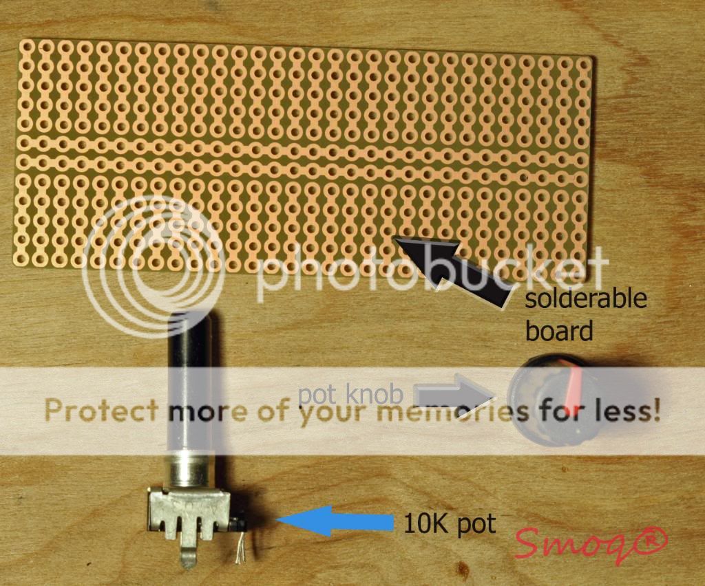
This is what you need to make a dimming circuit:
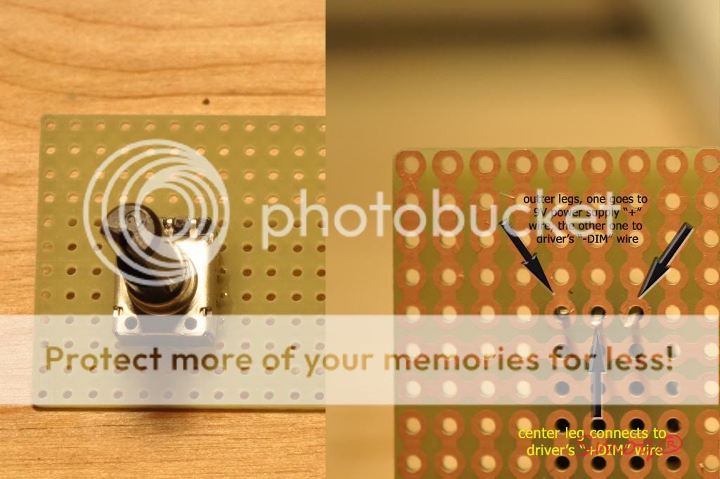
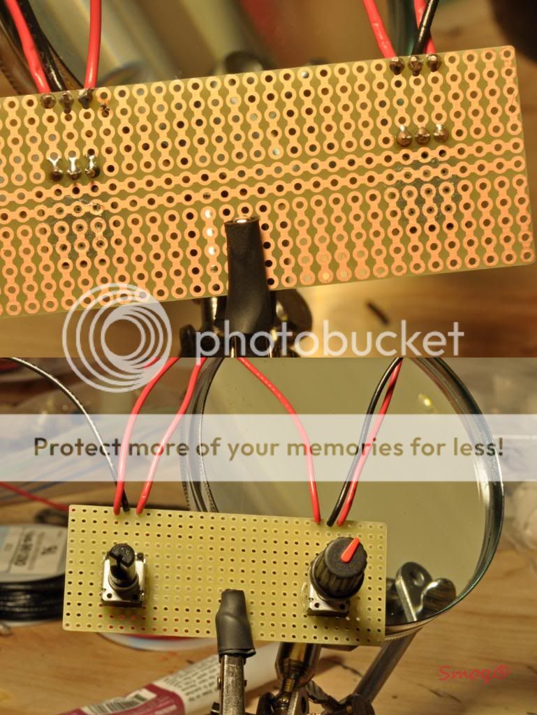
Solderable breadboard is very helpful here. First thing you need to do is glue the pots onto the board. I used IC Gel to do that. In the picture I marked each leg, follow that for every dimmer.
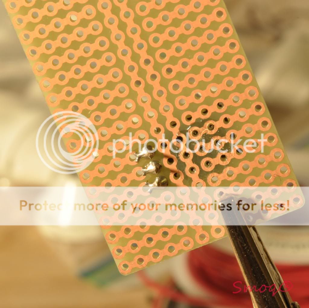
Next step is soldering the legs onto the board. Use just a little bit of solder and check with multimeter that there's no short between pot's prongs.
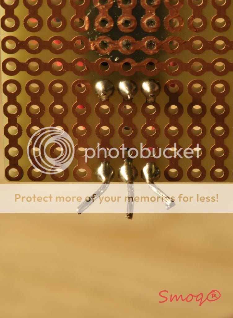
Finally, solder wires onto the board and make sure there is a connection between the wire and the pot's legs. The kind of board I used makes it easier as you can move the wires away from the pot.
That's it. I suggest marking each wire that goes to the pot and connect the dimmer circuit following the driver's scheme in the first post
V.Adjusting the LED's forwarding current
This is very important and should not be ignored. The safe maximum current for Cree Xp-g's, X-RE's and XP-E's is 1000mA=1A. If you run your leds on higher than safe current, you are reducing the lifespan of leds. In order to adjust forwarding current you need to wire up a multimeter set to measure amperage into your circuit. Here's a good read explaining how to connect a multimeter to measure current.
http://www.electronics-radio.com/articles/test-methods/meters/how-to-measure-current.php
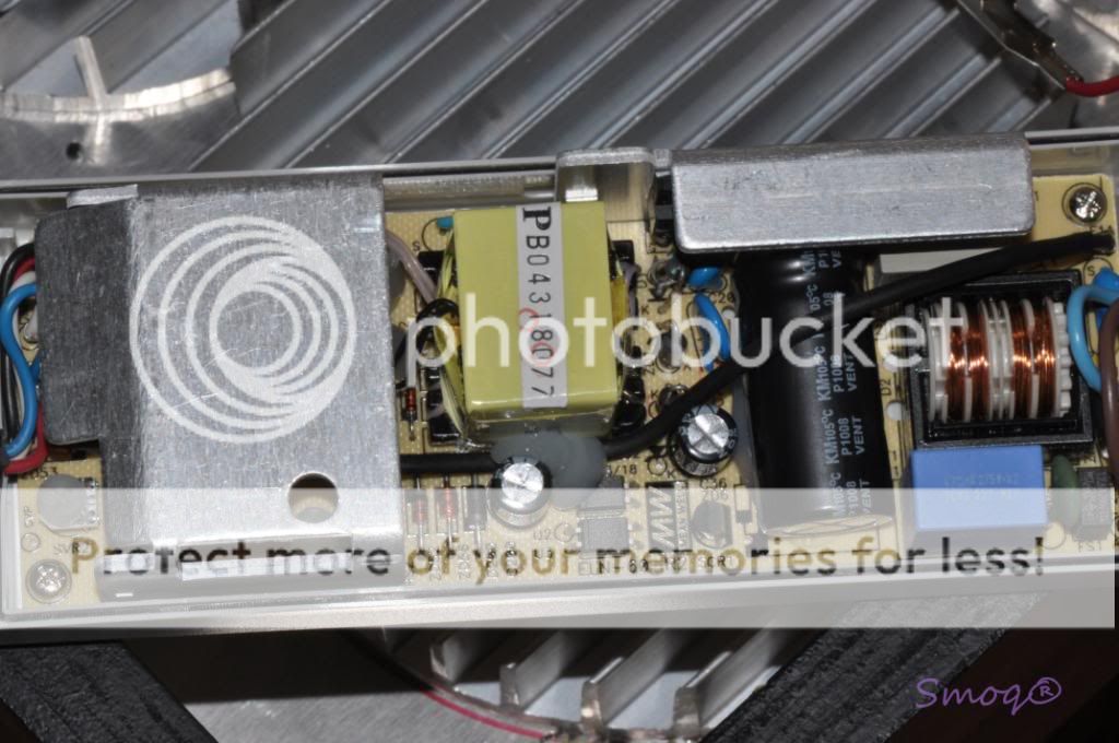
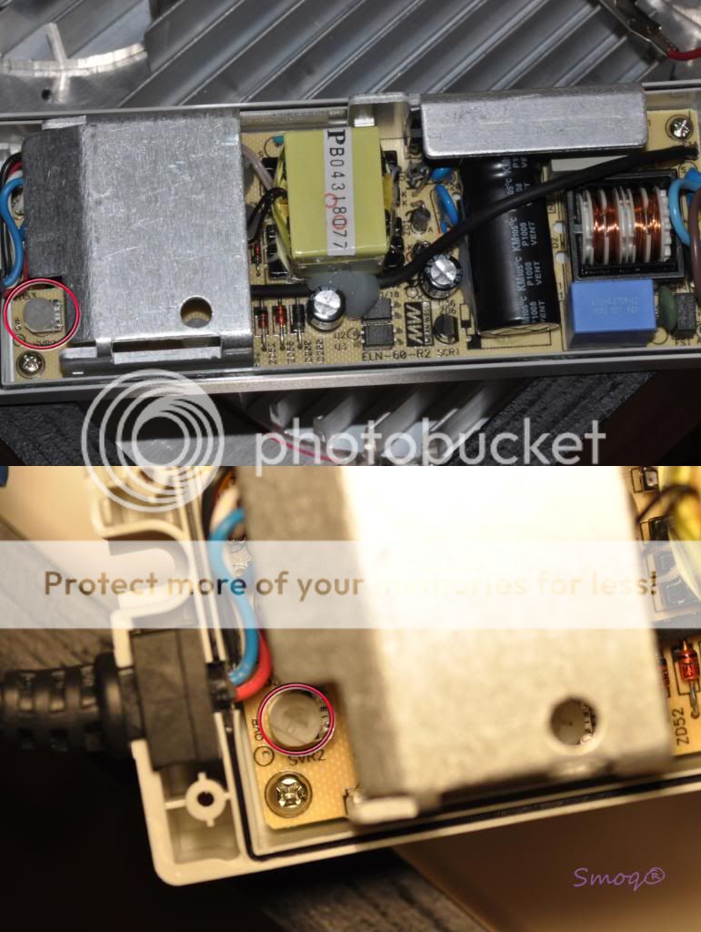
Next thing you have to do is unscrew the 4 screws in the meanwell drivers and remove the top cover. There is a plastic screw labeled SVR2 on the bottom-left side of the meanwell. By turning it clockwise, you increase the current and counterclockwise, decreasing. Make sure the current does not exceed 1000mA . I suggest driving the blue crees at 700mA and white ones at 900-1000mA. Here's a picture of meanwell 60-48D guts, please follow that to locate the SVR2 screw.
I hope that additional info will help you in your builds. Please comment and don't hesitate to ask questions. Happy New Year everyone. One more thing, I will ask moderators to move this post on top of the thread for better read.


